XR5FC/XR5SL Commercial Fire Panels Installation Guide 5 Zone Fire and Slave Panels with Built-in Communicators 2841 E.
MODELS XR5FC AND XR5SL COMMERCIAL FIRE PANELS INSTALLATION GUIDE FCC NOTICE This equipment generates and uses radio frequency energy and, if not installed and used properly in strict accordance with the manufacturer's instructions, may cause interference with radio and television reception.
TABLE OF CONTENTS Section Page Panel Specifications 1.1 1.2 1.3 1.4 1.5 1.6 1.7 Power supply ......................................................................................................................... 1 Communication ..................................................................................................................... 1 Panel zones ...........................................................................................................................
TABLE OF CONTENTS Section Page Class B (Style A) Fire Zones 11.1 11.2 11.3 11.4 Description ........................................................................................................................... 9 Operational parameters ....................................................................................................... 9 Zone response time ...........................................................................................................
Introduction Panel Specifications 1.1 Power supply Primary Power Input: 16.5 VAC 40VA (Model 320 wire-in) or 12/24 VDC from Fire Alarm Control Panel (FACP) Standby Batteries: One or two 12 VDC 7.0Ah Auxiliary Output: 500mA at 12 VDC Bell Output: 1.5 Amps at 12 VDC (XR5FC only) Smoke Detector Output: 100mA at 12 VDC (XR5FC only) All circuits inherent power limited except the red battery wire. 1.2 Communication Built-in SDLC Digital Dialer communication to DMP Model SCS-1 Receivers.
Introduction 2.2 Before you begin Before installing the XR5, we recommend you read through the entire contents of this guide. Familiarize yourself with the features of the panel and the key points to remember during the installation. Be sure to read and understand all of the caution statements printed in bold italics.
Introduction System Components 3.1 Description A basic XR5 system is made up of the alarm panel with built in communicator, an enclosure, a 16.5 VAC wire-in transformer, and a 12 VDC 7.0Ah battery. You can add up to two alphanumeric Security Command keypads and one LED Security Command keypad to the panel and also connect control and annunciating devices to the panel's Form C and annunciator outputs. Refer to section 6.6 in this guide when calculating power requirements. 3.
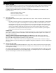
Introduction 3.3 XR5SL Wiring diagram The XR5SL system below shows some of the accessory devices you can connect for use in various applications. 377 Trouble Annunciator Module Refer to the Model 377 Installation Instructions (LT-0314). MODEL XR5 SILENCE/RESET PUSH FOR ONE SECOND J5 Silence/Reset Header Silence/Reset Button Telephone Connections Wiring on terminals 5 through 22 must exit to the right and maintain a 1/4" separation from the AC and battery positive wiring.
Installation Installation 4.1 Mounting the enclosure The metal enclosure for the XR5FC and XR5SL panels must be mounted in a secure, dry place to protect the panels from damage due to tampering or the elements. It is not necessary to remove the XR5FC or XR5SL PC board when installing the enclosure.
Installation 4.3 Mounting keypads Security Command keypads have removable covers that allow you to easily mount the base to a wall or other flat surface. After installing the keypad mounting anchors and bringing the keypad wiring from the panel through the wall, mount the base and connect the keypad wire harness leads to the keypad wiring. Next, attach the keypad wire harness connector to the pin connector on the keypad circuit board and install the cover.
Installation Secondary Power Supply 6.1 Battery terminals 3 and 4 Connect the black battery lead to terminal 4 on the panel and then to the negative terminal of the battery. The negative terminal connects to the enclosure ground internally through the XR5FC and XR5SL panel circuit board. Connect the red battery lead to terminal 3 on the panel and then to the positive terminal of the battery. Observe polarity when connecting the battery. The XR5FC and XR5SL panels are capable of recharging two 7.
Installation 6.6 XR5FC and XR5SL power requirements During AC power failure, the XR5FC and XR5SL panels, and all auxiliary devices connected to the panels, draw their power from the battery. All devices must be taken into consideration when calculating the battery standby capacity. Below is a list of the power requirements of the XR5FC and XR5SL panels.
Installation Keypad Data Bus 9.1 Description Terminals 7, 8, 9, and 10 of the XR5FC and XR5SL panels provide the keypad data bus to which you can connect Model 692F LED keypads as well as two alphanumeric Security Command keypads. 9.2 Terminal 7 - RED Terminal 7 provides 12 VDC keypad power for Security Command keypads. You can also connect 12 VDC auxiliary devices to terminal 7. The ground reference for terminal 7 is terminal 10. The maximum output is rated at 500mA on the XR5FC and XR5SL panels.
Installation 11.3 Zone response time Make A condition must be present on the zone for at least 500 milliseconds before it is detected by the XR5FC and XR5SL panels. Ensure detection devices used on the zones are rated for use with this delay. 11.4 Compatible 2-wire smoke detectors The table to the right lists those detectors meeting the compatibility requirements for use with the Class B (Stlyle A) zones on the XR5FC and XR5SL fire panels.
Installation Telephone RJ Connector 14.1 Description Connect the panel to the public telephone network by installing DMP 356 RJ Cables between the panel's J4 (MAIN) and J5 (BACKUP) connectors and the RJ31X or RJ38X phone jacks. 14.2 FCC registration The XR5FC and XR5SL panels comply with FCC part 68 and are registered with the FCC. Registration number: CCK USA - 18660 - AL - R Ringer Equivalence: 1.1B 14.3 Notification Registered terminal equipment must not be repaired by the user.
Installation UNIVERSAL UL and NFPA FIRE ALARM SPECIFICATIONS 18.1 Introduction The programming and installation specifications contained in this section must be completed when installing the XR5FC and XR5SL panels in accordance with any of the UL or NFPA fire standards. Additional specifications may be required by a particular standard. 18.2 Wiring All wiring must be in accordance with NEC, ANSI/NFPA 70. 18.
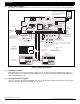
2841 E. Industrial Drive Springfield, MO 65802-6310 800-641-4282 Page 13 8 7 6 5 4 3 2 1 3.3k Ω DMP Model 866 37mA at 12 VDC S UL Listed, Polarized Indicating Devices. S S AUXILIARY POWER SUPPLY 1 2 AC 3 B+ 4 B– 5 Power Supply Trouble Contacts N/C 6 7 S BELL SMK RED J5 MAIN BACKUP Each 866 Notification Circuit Module in alarm draws up to 35mA from its terminal 3 alarm input.
6 Bell A + Output - Page 14 3.
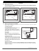
Installation 21.3 Multiple 866 Notification Circuit Modules for zoned annunciation To additional ten 866 Notification Circuit Modules. Up to a maximum of thirteen 866 modules on the XR5FC panel. Modules must be installed in a Model 340FC, 340SL, 349, or 350 enclosure connected by no more than 20 feet of conduit.
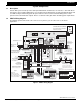
Installation 21.4 Remote Station reversing relay connection MODEL XR5 MAIN BACKUP SILENCE/RESET PUSH FOR ONE SECOND J5 J4 PANEL RESET Telephone Connections OUTPUT 2 EPROM Socket OUTPUT 1 U21 J11 1 2 AC AC 3 B+ 4 B– 5 6 7 BELL SMK RED 8 9 10 11 12 13 S S S S S Z2+ S S 17 Z2 – S W S 16 15 14 YEL GRN BLK Z1A+ Z1A– Z1B+ Z1B– S S Z3+ 18 19 Z3 – S Z4+ 20 S S 3.3k Ω 21 Z4 – Z5+ 22 S S 3.3k Ω N/C COM N/O N/C COM N/O Z5 – 1 2 3 4 J12 S 3.
2841 E. Industrial Drive Springfield, MO 65802-6310 800-641-4282 Page 17 8 7 6 5 4 3 2 1 3.3k Ω Notification Circuit Module DMP Model 866 37mA at 12 VDC Bell Trouble Bell Trouble Bell Output - Bell Output + Bell Power Input Alarm Input Ground Auxiliary Power S 10k Ω EOL Resistor DMP Model 308 Remote DPDT Relay S Modules must be installed in a Model 340FC, 340SL, 349, or 350 enclosure connected by no more than 20 feet of conduit.
XR5FC/XR5SL Installation Guide 2841 E. Industrial Drive Springfield, MO 2841 E. Industrial Drive Springfield, Page 18MO 65802-6310 800-641-4282 Form C contacts activate on AC power fail. Use on XR5SL in DC mode only. Must delay AC power fail 6 to 12 hours. Form C or A contacts activate on Supervisory condition. Form C trouble contacts activate on General Trouble. General Trouble must not be used to indicate AC power fail unless it can be delayed 6 to 12 hours.