Installation Guide XTL/XTLC Panel
MODEL XTL/XTLC INSTALLATION GUIDE FCC NOTICE This equipment has been tested and found to comply with the limits for a Class B digital device, pursuant to part 15 of the FCC Rules. These limits are designed to provide reasonable protection against harmful interference in a residential installation. This equipment generates, uses and can radiate radio frequency energy and, if not installed and used in accordance with the instructions, may cause harmful interference to radio communications.
Table of Contents Panel Specifications 1.1 1.2 1.3 1.4 1.5 Power Supply.........................................................1 Communication......................................................1 Keypads.................................................................1 Number of Zones....................................................1 Enclosure Specifications..........................................1 Introduction 2.1 2.2 2.3 System Configurations............................................
Table of Contents Household Burglar-Alarm System Units ANSI/UL 1023 16.1 16.2 16.3 16.4 16.5 16.6 16.7 16.8 Bell Cutoff..............................................................7 Entry Delay............................................................7 Exit Delay..............................................................7 Wireless External Contact........................................7 Wireless Supervision Time.......................................7 Wireless Audible Annunciation...................
system components Panel Specifications 1.1 Power Supply Input: 12 VDC Standby Battery: 3.7 VDC Lithium All circuits inherent power limited 1.2 Communication The XTL/XTLC contains built-in Cellular communication to DMP Model SCS-1R or SCS-VR Receivers. Cellular Service is required before using the XTL/XTLC for signal transmission. The XTL panel is provided with a SIM card for activation, while the XTLC does not require the use of a SIM card.
Introduction System Components 3.1 Accessory Devices DMP Two-Way Wireless Devices 1100R Repeater 1101 Universal Transmitter *1131 Recessed Contact 1135/*1135DB Siren Provides additional range for wireless devices. Provides both internal and external contacts that may be used at the same time to yield two individual reporting zones from one wireless transmitter. Provides one external contact.
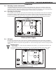
system components 4.1 4.2 Installation Mounting Location Information A location should be selected that is centrally located between the 1100 Series transmitters used in the installation. Install the XTL/XTLC away from metal objects. Mounting the panel on or near metal surfaces impairs performance. When selecting the proper mounting location of a transmitter, refer to the LED Survey Operation section of the specific installation guide for the transmitter being installed.
Installation Secondary Power Supply 6.1 Standby Battery The XTL/XTLC rechargeable battery is used to provide backup battery power when DC power is not available. The battery is intended for backup power only and not to operate the panel on a daily basis. If the battery is low, or not plugged into the J1 battery connector, a low battery condition is indicated by the panel. Note: If removing the panel from service, disconnect the backup battery from the panel connector. 6.
Installation LED Operation 7.1 Backlit Logo The backlit logo indicates the Power and Armed status of the panel. Depending on the operation, the LED displays in Red or Green as listed in the table.
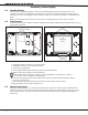
Installation 11.1 Mounting Keypads Wireless Keypads DMP keypads have removable covers that allow the base to be mounted on a wall, desk stand or other flat surface using the screw holes provided on each corner. 11.2 Wireless Keypad Association Enable Wireless Keypad Association operation on both the keypad and panel. To enable association operation in the keypad, access the Installer Options Menu (3577 (INST)). The keypad logo LEDs turn off until association is successful.
COMPLIANCE Listed Compliance Specifications 15.1 Introduction The programming and installation specifications contained in this section must be completed when installing the XTL/XTLC in accordance with any of the ANSI or SIA burglary standards. Additional specifications may be required by a particular standard. 15.2 Use Marking Commercial Central Station, Household Burglar and Fire Control Unit. 15.
COMPLIANCE Central Station Burglar Alarm Units ANSI/UL 1610 17.1 Supervision Commercial Burglary is provided when the Cell Check-in and Fail Time time is set to 3 minutes. Note: The SecureCom Wireless text plan selected for the panel should match or exceed the programmed Monthly Limit or additional cellular charges may apply. 17.2 Remote Disarm REMOTE DISARM must be programmed as NO. 17.3 Central Station MESSAGE TO TRANSMIT programming for zones must not be set to LOCAL (L).
COMPLIANCE False Alarm Reduction Programmable Options ANSI/SIA CP-01-2010 19.1 Shipping Defaults and Recommended Programming SIA CP-01 FEATURE PARAGRAPH # AND DESCRIPTION DMP PROGRAMMING GUIDE LT‑1108 SECTION # REQUIREMENT Required (Programmable) RANGE SHIPPING DEFAULT 60 Seconds All Individual keypads may keypads be disabled per zone enabled For re-entry during exit Enabled time 45 sec. - 250 sec. 4.2.2.1 Exit Time 8.6 Exit Delay 4.2.2.2 Progress Annunciation 13.13 Prewarn Address Allowed 4.2.2.
Revisions Revisions to This Document Revisions This section explains the changes that were made to this document during this revision. This section lists the version, section number with heading, and a quick summary of the change. Ver. Section Number and Heading 1.06 18.3 Wireless External Contact Removed 1101, 1102, and 1105 section 1.05 Entire document Added references to XTL/XTLC 3.1 Accessory Devices Added reference for 1135DB Siren 9.
XTL/XTLC Installation Guide Digital Monitoring Products 11
Certifications California State Fire Marshall (CSFM) ANSI/SIA CP-01 False Alarm Reduction ANSI/UL 1023 Household Burglar ANSI/UL 985 Household Fire Warning ANSI/UL 1610 Central Station Burglar (Cellular) FCC Cellular Approvals for XTLC Cellular FCC Part 15: MIVCNN0301 Cellular Industry Canada: 4160A-CNN0301 800 - 641 - 4282 Intrusion • fire • Access • Networks www.dmp.com 2500 North Partnership Boulevard Designed, Engineered and Assembled in U.S.A.