
Installation guide

Digital Monitoring Products XR2500F Installation Guide
vi
REVISIONS
XR2500F Installation Guide Digital Monitoring Products
1
INTRODUCTION
Introduction
1.1 Overview
The DMP XR2500F Addressable Fire Alarm Control Panel (FACP) is an expandable 24 VDC Fire Alarm Control
with built-in DACT and LCD Fire Command Center keyboard with membrane keyswitch. A complete system
can provide a total of 574 programmable inputs and outputs for commercial and industrial re alarm service.
The 24 VDC 4 Amp notication appliance power is distributed between two class B style W NAC outputs.
Additional NAC outputs can be added with conventional supervision modules or addressable power supply/
boosters. Addressable smoke detectors and input modules round out the XR2500F to deliver a truly exible
and expansive re detection and notication system. The Fire Alarm Control Panel is shipped pre-wired
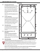
in a red metal enclosure housing the necessary components to monitor and control re alarm notication
appliances. The enclosure dimensions are as follows: 32” H x 14.5” W x 4” D. The lid adds about 0.5” to
each side.
1.2 System Components
The XR2500F FACP consists of the following components:
• One Model XR2500F Command Processor panel • One Model 893A Dual Phone Line module
• Two Model 866 Class B Style W NAC modules • One Model 630F PCB and membrane switch
• One Model 504-24 VDC Power Supply • One 28 VAC transformer
• One 16 VAC, 56 VA transformer • Two Model 305 Plug-in Relays
• One Model 481 Zone Expansion Interface Card • One Metal Backplate
1.3 Power Specications
Command Processor:
Transformer Input: 16 VAC 56 VA
Standby battery: 12 VDC, 1.0 Amps Max. charging current
Auxiliary power: 12 VDC output at 1.5 Amp Max
All circuits are inherent Power Limited except red battery wires.
NAC Output:
24 VDC 4 Amps shared between NAC 1 and 2
Note: For UL installations, the total current combined from Auxiliary Power cannot exceed:
1.3 Amps with a 50 VA transformer, 1.0 Amp Max for Auxiliary Power
1.9 Amps with a 56 VA transformer, 1.0 Amp Max for Auxiliary Power.
1.4 Before You Begin
Before installing the XR2500F, we recommend you read through the entire contents of this guide.
Familiarize yourself with the panel features and the key points to remember during the installation. Be sure
to read and understand all of the caution statements printed in bold italics.
1.5 About this Guide
The information in this guide is organized into ve sections: Table of Contents, Introduction, Installation,
Compliance, and System Wiring Diagrams.
• The Table of Contents at the front lists the headings and subheadings used throughout each guide section.
• The Introduction section provides an overview of the XR2500F and this document.
• The Installation section begins with enclosure mounting instructions. Wiring diagrams for each component
also appear in this section.
• The Compliance section lists all UL listings the XR2500F currently follows.
• The System Wiring Diagrams provide illustrations of typical XR2500F systems.
1.6 How to use this Guide
To locate information about the XR2500F installation, refer to the Table of Contents at the front of this
guide. Find the subject heading that best describes the information you need and turn to the section
number shown to the left of the heading. If you cannot nd the information you need under that heading,
scan through a few of the headings and read the text under those that sound similar.