
Installation guide

Digital Monitoring Products XR2500F Installation Guide
vi
REVISIONS
XR2500F Installation Guide Digital Monitoring Products
1
INTRODUCTION
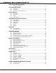
Revisions to This Document
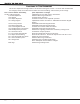
This section explains the changes made to this document during this revision. It lists the date and identies
the change(s) made, the related section number and section heading, and a summary of the change.
Date Section Number and Heading Quick Explanation of Changes
10/05 2.6 Wiring Diagram Updated End-of-Line (EOL) resistor information.
6.5 LX-Bus Expansion Added LX-Bus wiring information.
12.6 Outputs Claried output operation.
13.2 Output Expansion Claried 716 and 717 zone expander operation.
14.1 Wiring Diagram Updated EOL resistor information. Added 693 and Thinline keypad
models.
14.3 Accessory Devices Added 693 and Thinline keypad models.
14.4 Mounting Keypads Added 693 and Thinline keypad models.
14.5 Connecting Bus Devices Claried J22 on-board LX-Bus information.
15.7 Standby Battery Calculations Added 693 and Thinline keypad models.
15.8 Standby Battery Selection Added notes regarding transformers and battery recharge time.
16.1 Terminals 5 and 6 Claried bell output operation.
21.1 Dry Contact Relay Outputs Removed unsupported functions from listing.
21.3 Output Harness Wiring Removed 431 reference. Revised J2 Output Color Code wire colors.
23.1 J23 6-Pin Header Description Added J16 reset information.
24.1 J22 LX-Bus Description Added LX-Bus wiring information.
39.1 through 39.5 Added New York City MEA Specications.
Note: Subsequent section numbers changed.
Back Page Added Listings and Approvals.