
Installation guide

Digital Monitoring Products XR2500F Installation Guide
ii
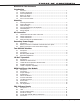
TABLE OF CONTENTS
XR2500F Installation Guide Digital Monitoring Products
iii
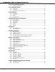
TABLE OF CONTENTS
Interconnect Wiring Harness
9.1 Interconnect Harness................................................................................... 12
Fire Command Center
10.1 Description.................................................................................................. 13
10.2 Connection.................................................................................................. 13
10.3 Remote Fire Command Center...................................................................... 13
Panel Features
11.1 Description.................................................................................................. 14
11.2 Connection ................................................................................................. 14
11.3 Relays ....................................................................................................... 14
11.4 Zone Reference ........................................................................................... 14
XR2500F Product Specications
12.1 Power Supply .............................................................................................. 15
12.2 Communication ........................................................................................... 15
12.3 Panel Zones ................................................................................................ 15
12.4 Keypad Bus ................................................................................................. 15
12.5 LX-Bus™ ..................................................................................................... 15
12.6 Outputs ...................................................................................................... 15
Expansion
13.1 Zone Expansion ........................................................................................... 16
13.2 Output Expansion ........................................................................................ 16
Accessory Devices
14.1 Wiring Diagram ........................................................................................... 17
14.2 Lightning Protection..................................................................................... 17
14.3 Accessory Devices ....................................................................................... 18
14.4 Mounting Keypads and Zone Expansion Modules............................................ 19
14.5 Connecting LX-Bus and Keypad Bus Devices .................................................. 19
Battery Information
15.1 Battery Only Restart .................................................................................... 20
15.2 Battery Replacement Period ......................................................................... 20
15.3 Discharge/Recharge..................................................................................... 20
15.4 Battery Supervision...................................................................................... 20
15.5 Battery Cutoff.............................................................................................. 20
15.6 XR2500F Power Requirements ...................................................................... 20
15.7 XR2500F Standby Battery Calculations .......................................................... 21
15.8 Standby Battery Selection ............................................................................ 23
Bell Output
16.1 Terminals 5 and 6 ........................................................................................ 24
Keypad Bus
17.1 Description.................................................................................................. 24
17.2 Terminal 7 - RED ......................................................................................... 24
17.3 Terminal 8 - YELLOW ................................................................................... 24
17.4 Terminal 9 - GREEN ..................................................................................... 24
17.5 Terminal 10 - BLACK .................................................................................... 24
17.6 J8 Programming Connection......................................................................... 24
17.7 OVC LED..................................................................................................... 24
Smoke and Glassbreak Detector Output
18.1 Terminals 11 and 12 .................................................................................... 25
18.2 Current Rating............................................................................................. 25