
Installation guide

Digital Monitoring Products XR2500F Installation Guide
30
INSTALLATION
XR2500F Installation Guide Digital Monitoring Products
31
INSTALLATION
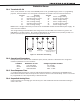
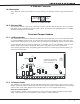
J22 LX-Bus Expansion Connector
24.1 Description
J22 LX-Bus and J21 RS-232 connectors cannot be used at the same time. Either use J21 to connect a serial
device for PC Log Reporting, or use J22 to connect an LX-Bus device. This is determined by where you install
the jumper on J23 6-Pin Header. Reset the panel using J16 jumper to activate selected J23 operation.
Note: Do NOT use shielded wire when using the LX-Bus. Do NOT connect the wires from the 4-wire harness
to the panel terminals.
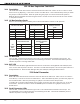
24.2 LX-Bus Interface Cards
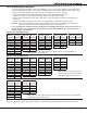
Refer to the following tables to identify zone locations and numbers relative to J22 operation.
J22 LX-Bus Enabled
AND
One Interface Card
OR
461 Adaptor Card and
Multiple Interface
Cards
LX-Bus Zone Numbers LX-Bus Zone Numbers LX-Bus Zone Numbers
1 500-599 2 600-699 2 (A) 600-699
3 (B) 700-799
4 (C) 800-899
5 (D) 900-999
J22
LX-Bus
NOT
Enabled
One Interface Card
OR
461 Adaptor Card and
Multiple Interface
Cards
LX-Bus Zone Numbers LX-Bus Zone Numbers
1 500-599 1 (A) 500-599
2 (B) 600-699
3 (C) 700-799
4 (D) 800-899
5 (E) 900-999
24.3 LX-Bus LEDs
The two LEDs, located near the bottom-right corner of J21 indicate data transmission and receipt. The
top LED ashes green to indicate the panel is transmitting LX-Bus data. The bottom LED ashes yellow to
indicate the panel is receiving LX-Bus data.
24.4. OVC LED
The Overcurrent LED (OVC) lights Red when the devices connected to the Keypad Bus and LX-Bus(es) draw
more current than the panel is rated for. The OVC is located above Outputs 1 and 2 on the panel and turns a
steady Red when lit. When the OVC LED lights Red, the LX-Bus(es) and keypad bus shut down.
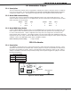
J21 Serial Connector
25.1 Description
Note: J22 LX-Bus and J21 RS-232 connectors cannot be used at the same time. Either use J21 to connect a
serial device, or use J22 to connect an LX-Bus device. This is determined by where you install the jumper on
the J23 6-Pin Header. Reset the panel using J16 jumper to activate selected J23 operation.
To enable J21 to operate in RS-232 mode place a jumper on the two pins next to the letter “R” on the J23
6-Pin header. The Serial Connector allows the XR2500F panel to transmit PC Log Reports directly to an
RS-232 device.
25.2 Serial Connector LEDs
The two LEDs, located near the bottom-right corner of J21 indicate data transmission and receipt. The
top LED ashes green to indicate the panel is transmitting serial data. The bottom LED ashes yellow to
indicate the panel is receiving serial data.