
Installation guide

Digital Monitoring Products XR2500F Installation Guide
28
INSTALLATION
XR2500F Installation Guide Digital Monitoring Products
29
INSTALLATION
J11 Annunciator Outputs
22.1 Description
The four annunciator outputs can be programmed to indicate the activity of the panel zones or conditions
occurring on the system. Annunciator outputs do not provide a voltage but instead switch-to-ground a
voltage from another source. The outputs can respond to any of the conditions listed in section 22.1.
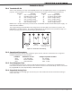
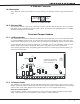
22.2 Model 300 Harness Wiring
Access the open collector outputs by installing DMP 300 Harness on the 4-pin header labeled J11. The
output locations are shown below. For UL applications, devices connected to the outputs must be located
within the same room as the panel.
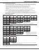
Output Color Wire Output Color Wire
3 Red 1 5 Green 3
4 Yellow 2 6 Black 4
22.3 Model 860 Relay Module
Connect a Model 860 Relay Module to the J11 on the XR2500F panel to provide relays for outputs 3-6. Use
these relays for electrical isolation between the alarm panel and other systems or for switching voltage
to control various functions. Power is supplied to the relay coils from a single wire connected to the
panel auxiliary power terminal 7. The module includes one relay and provides three additional sockets for
expansion of up to four relays. Mount the 860 inside the panel enclosure using the 3-hole pattern and plastic
standoffs. Refer to the 860 Module Install Sheet (LT-0484) as needed.
Model 305 Relay Contact Rating: 1 Amp at 30 VDC
J23 6-Pin Header
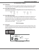
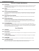
23.1 Description
The XR2500F Command Processor™ panel supports RS-232, LX-Bus and future expansion operation. These
operations cannot function at the same time. Install a jumper on one pair of J23 headers to indicate how
the panel is programmed to operate. Refer to the table below when installing a jumper on J23. When a
jumper is installed or moved on the 6-pin header, briey reset the panel using the J16 jumper to activate
the selected operation.
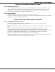
J23 6-Pin Header
Letter Operation
R Standard RS-232
L LX-Bus
X Future Expansion
LEDs
Xmi
t
Receiv
e
J22
LX-Bus
J2
3
J2
1
RS-232
R
L
X
Overcurrent
LED
Figure 14: J23 6-Pin Header