
Installation guide

Digital Monitoring Products XR2500F Installation Guide
28
INSTALLATION
XR2500F Installation Guide Digital Monitoring Products
29
INSTALLATION
Dry Contact Relay Outputs
21.1 Description
The XR2500F panel provides two auxiliary SPDT relays with the two DMP Model 305 relays in K6 (Output 1)
and K7 (Output 2) and a Model 431 Output Harness on the J2 6-pin Header. Each relay provides one SPDT set
of contacts that can be operated by any of the functions listed below:
1) Activation by zone condition: Steady, Pulsing, Momentary, and Follow
2) Activation by 24-hour 7-day schedule: One on and one off time a day for each relay
3) Manual activation from the Security Command keypad menu
4) Communication failure
5) Armed area annunciation
6) Fire Alarm or Fire Trouble
7) Ambush Alarm
8) Exit and Entry timers
9) System Ready
10) Late to Close
Refer to the XR500 Series Programming Guide (LT-0679) for specic information.
21.2 Contact Rating
The Model 305 relay contacts are rated for 1 Amp at 30 VDC resistive. You can connect auxiliary power to
the Relay Output 1 common terminal by installing the gray harness wire to terminal 7. Current draw for all
connected devices must not exceed the panel maximum current rating.
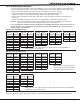
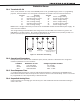
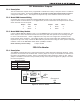
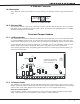
21.3 Output Harness Wiring
The Output Harness is pre-installed on the 6-pin header labeled J2. Output 2 uses the top three prongs,
and Output 1 uses the bottom three prongs. Outputs 1 and 2 are prewired to the 866 NAC modules located
within the XR2500F enclosure. For reference, the wire harness and contact locations are shown below:
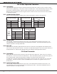
Contact Color
Output 1 normally closed Violet
Output 1 common Gray
Output 1 normally open Orange
Output 2 normally closed Blue
Output 2 common White
Output 2 normally open Yellow