
Installation guide

Digital Monitoring Products XR2500F Installation Guide
24
INSTALLATION
XR2500F Installation Guide Digital Monitoring Products
25
INSTALLATION
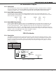
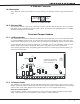
Smoke and Glassbreak Detector Output
18.1 Terminals 11 and 12
Terminal 11 supplies positive 12 VDC to power 4-wire smoke detectors and other powered devices. This
output can be turned off by the user for ve seconds using the Sensor Reset User Menu option to allow
latched devices to reset. Terminal 12 is the ground reference for terminal 11. See LT-0164 for a list of
approved 4-wire smoke detectors and power supervision relays.
18.2 Current Rating
The Output current from terminal 11 is shared with terminals 7, 25, and 27.
The total current draw of all devices powered from the panel must be included with terminal 11 calculations
and must not exceed the maximum output rating.
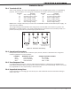
Powered Zones for 2-Wire Smoke Detectors
19.1 Terminals 25–26 and 27–28
Panel terminals 25 through 28 provide two resettable Class B, Style A, 2-wire powered zones. For
programming purposes the zone numbers are 9 and 10.
Note: The maximum wire length for either zone 9 or zone 10 is 3000 feet using 18 AWG or 1000 feet using 22
AWG.
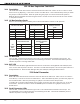
When using 725 Zone Expansion Modules, use included, UL Listed 6.8k Ohm EOL resistors. The UL
compatibility identier for the zones using 725 Zone Expansion Modules is B. When using 715 Zone
Expansion modules, use UL Listed 3.3k Ohm EOL resistors, Model 309. For all other zone expansion modules,
use UL Listed 1.0k Ohm Model 310 EOL resistors. The UL compatibility identier for the zones is A.
Note: Do not mix detectors from different manufacturers on the same zone.
Caution: Performing a Sensor Reset momentarily drops power to the devices on Zones 9 and 10. The panel
views these zones (9 and 10) as “Open” while the power is absent.