
Installation guide

Digital Monitoring Products XR2500F Installation Guide
24
INSTALLATION
XR2500F Installation Guide Digital Monitoring Products
25
INSTALLATION
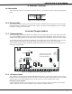
Bell Output
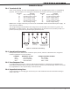
16.1 Terminals 5 and 6
Terminal 5 supplies positive 12 VDC to power alarm bells or horns. This output can be steady, pulsed, or
temporal depending upon the Bell Action specied in Output Options. Terminal 6 is the ground reference
for the bell circuit. This supervised output detects 10k Ohms or less as normal. The indicating appliance
can supply this resistance. If using a horn or siren, a 1k Ohm 1/2 W EOL resistor (provided) should be added
across the bell circuit to provide supervision.
Keypad Bus
17.1 Description
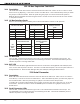
XR2500F panel terminals 7, 8, 9, and 10 are for the keypad bus. In addition to Fire Command Centers and
Remote Fire Command Centers, you can connect up to sixteen supervised keypads and multiple unsupervised
keypads to the XR2500F. In addition to Security Command keypads, you can also connect any combination
of zone expansion modules, 5845LX Glassbreak detectors, and 6155LX PIRs to the data bus. Refer to the
specic device Installation sheet for the maximum number of keypad Bus devices.
Refer to the section titled LX-Bus for complete information about the LX-Bus 4-pin header and expansion
slot.
Note: Do not use shielded wire for LX-Bus/Keypad Bus circuits.
17.2 Terminal 7 - RED
This terminal supplies positive 12 VDC to power Fire Command Centers and zone expansion modules.
Terminal 7 also supplies power for any auxiliary device. The ground reference for terminal 7 is terminal 10.
The output current is shared with the smoke power output on terminal 11 and Zones 9 and 10. Current draw
for all connected devices must not exceed the panel maximum current rating.
17.3 Terminal 8 - YELLOW
Terminal 8 receives data from keypads and zone expansion modules. It cannot be used for any other
purpose.
17.4 Terminal 9 - GREEN
Terminal 9 transmits data to keypads and zone expansion modules. It cannot be used for any other purpose.
17.5 Terminal 10 - BLACK
Terminal 10 is the ground reference for Fire Command Centers, zone expansion modules, and all auxiliary
devices being powered by terminal 7.
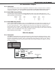
17.6 J8 Programming Connection
A 4-pin header (J8) is provided to connect a keypad when using a DMP Model 330 Programming Cable. This
provides a quick and easy connection for panel programming.
You may also use the J8 Programming Header to connect Keypad Bus devices. This is an alternative to
connecting keypad bus devices to terminals 7, 8, 9, and 10.
17.7 OVC LED
The Overcurrent LED (OVC) lights Red when the devices connected to the Keypad Bus and LX-Bus(es) draw
more current than the panel is rated for. The OVC is located above Outputs 1 and 2 on the panel and turns a
steady Red when lit. When the OVC LED lights Red, the LX-Bus(es) and Keypad bus are shut down.