
Installation guide

XR2500F Installation Guide Digital Monitoring Products
i
TABLE OF CONTENTS
Revisions to This Document
Introduction
1.1 Overview ...................................................................................................... 1
1.2 System Components ...................................................................................... 1
1.3 Power Specications ...................................................................................... 1
1.4 Before You Begin ........................................................................................... 1
1.5 About this Guide............................................................................................ 1
1.6 How to use this Guide.................................................................................... 1
Mounting
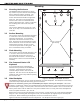
2.1 Mounting the Enclosure.................................................................................. 2
2.2 Surface Mounting .......................................................................................... 2
2.3 Flush Mounting.............................................................................................. 2
2.4 Fire Command Center LCD Keyboard............................................................... 2
2.5 Metal Backplate ............................................................................................. 2
2.6 Wiring Diagram ............................................................................................. 3
AC Connection
3.1 Transformers and AC Power Connection .......................................................... 4
3.2 28 VAC Transformer....................................................................................... 4
3.3 16 VAC Transformer ...................................................................................... 4
3.4 Earth Ground from the XR2500F Panel ........................................................... 4
Secondary Power Supply
4.1 Description.................................................................................................... 5
4.2 Battery Connection to XR2500F Command Processor panel............................... 5
4.3 Battery Connection to the 504-24 Power Supply............................................... 5
Two 866 NAC Modules
5.1 Description.................................................................................................... 6
5.2 Connection.................................................................................................... 6
5.3 Bell Silence/Bell Trouble ................................................................................. 6
5.4 Notication Appliances .................................................................................. 7
LX-Bus™ Operation
6.1 Description.................................................................................................... 8
6.2 XR2500F On-board LX-Bus ............................................................................ 8
6.3 LX-Bus 481 Zone Expansion Interface Card...................................................... 8
6.4 Installing the 481 Card................................................................................... 8
6.5 LX-Bus™ Expansion Capability ........................................................................ 8
893A Dual Phone Line Module
7.1 Description.................................................................................................... 9
7.2 Connection.................................................................................................... 9
7.3 Jumper Settings ............................................................................................ 9
7.4 Digital Dialer ................................................................................................. 9
7.5 Phone Line Monitor........................................................................................ 9
7.6 Processor Fail Buzzer ..................................................................................... 9
7.7 J10 893A Connector....................................................................................... 9
7.8 Ground start.................................................................................................. 9
7.9 Notication ................................................................................................. 10
7.10 FCC Registration ......................................................................................... 10
504-24 Power Supply
8.1 Description.................................................................................................. 11
8.2 LEDs .......................................................................................................... 11
8.3 504-24 Condition Chart ................................................................................ 11
8.4 504-24 UL Listings....................................................................................... 11
8.5 24 VDC NAC Standby Battery Calculations ..................................................... 11
8.6 Connection.................................................................................................. 12