
Installation guide

Digital Monitoring Products XR2500F Installation Guide
16
INSTALLATION
XR2500F Installation Guide Digital Monitoring Products
17
INSTALLATION
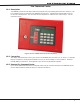
Accessory Devices
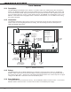
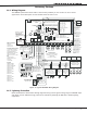
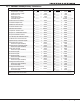
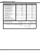
14.1 Wiring Diagram
The XR2500F system below shows some of the accessory modules you can connect for use in various
applications. A brief description of each module follows in section 14.3.
Heat detectors, pull
stations, or any other
contact devices listed
for
Fire Protective
Signaling can be
connected to zones
9 and 10.
Zo
nes 9 and 10 and
Model 715 compatibility
identifier: A
Maximum operating
range: 9.8 VDC to
14.0 VDC.
Class B (Style A).
DMP Transformers
Model 322
16 VAC 56 VA
Class 2 Wire-in.
Secondary Power Supply
1.0 Amps Max. charging
current. Use only 12 VDC
rechargeable batteries.
DMP Models 365, 366, 367,
368, or 369. Replace
batteries every 3 to 5 years.
Bell
12 VDC nominal
Minimum cutoff time is
5 minutes.
1.5 Amp Max
Keypads
Models 690/690F
77mA at 12 VDC
Models 790/790F/791
77mA at 12 VDC
Model 693/793
92mA at 12 VDC
Model 630F
63mA at 12 VDC
Model 7060
80mA at 12 VDC
Model 7070
72mA at 12 VDC
Model 7063
86mA at 12 VDC
Model 7073
93mA at 12 VDC
Auxiliary Power
Total current combined from
terminals 7, 11, 25, and 27
1.5 Amp Max
10.2 VDC to 14.0 VDC
UL Listed Resistors
1.0k Ohm - DMP Model 311
3.3k Ohm - DMP Model 309
10K Ohm - DMP Model 308
Bell cutoff time
range is 5 to 99
minutes marchtime
and non-coded.
AC
1 2 3 4 5 6 7 8 10 11 12 13 14 15 16 17 18 199 20 21 22 23 24 25 26 27 2
8
+B BELL GND SMK GNDRED YEL GRN BLK Z1 Z2 Z3 Z4 Z5 Z6 Z7 Z8 Z9+ Z9– Z10+ Z10–AC –B GND GND GNDGND
K6 K7
Output 1 Output 2
J3
Phone Line
J10
J22
LX-Bus
Bat
tery
Start
J2
3
J2
1
RS-232
Po
wer
LED
J8
PROG
J4
Tamper
J16
Reset
Out1 Out2
Outputs 3-6
J1
1
3
4
5
6
J2
"
J1
Ethernet
R
L
X
Link LED
Activity LED
OV
C
XR2500F
Command Processor™
Pane
l
POWER
ARMED
1k Ohm 1k Ohm 1k Ohm
DISARM
AR
M
J6
3.3k Ohm
3.3k Ohm
3.3k Ohm
3.3k Ohm
1k Ohm
Form C Relays (J2
)
Output Color Code
Output 2 N/O Yello
w
Output 2 Com White
Output 2 N/C Blue
Output 1 N/O Orange
Output 1 Com Gray
Output 1 N/C Violet
Annunciator Outputs (J11
)
Output Color Code
Output 3 Re
d
Output 4 Yello
w
Output 5 Green
Output 6 Blac
k
AC Wiring must be in conduit and exit
out the left side of the enclosure.
Wiring on terminals 5 through 22 must
exit right and maintain 1/4" separation
from the AC and battery positive wiring.
Front
Tamper
Rear
Tamper
s
16 to 18 gauge wire
Maximum AC Wire distance
with 16 gauge wire: 70 feet
with 18 gauge wire: 40 feet
RED
BLACK
Cold Water
Pipe Earth
Ground
Bell
Zone 1
Zone
2
Zone
3
Zone 4
Zone 5
Zone 6
Zone 7
Zone 8
3.3k
Ohm
Resistor
3.3k
Ohm
Resistor
Zone Expander
Model 715
7mA @ 12 VDC
Models 715-8, 715-1
6
20mA @ 12 VDC
Smoke
Detector
Use UL Listed Power
Supervision Relay
rated at 12 VDC.
1k Ohm
s
= Supervised Circuit
Zone
9
Zone
10
22 gauge minimum
22 gauge minimum
22 gauge minimum
22 gauge minimum
RED
YELLOW
GREE
N
BLAC
K
1k Ohm 1k Ohm
1k Ohm
Zone Expander
Model 714
7mA @ 12 VDC
Models 714-8, 714-1
6
20mA @ 12 VDC
RED
YELLOW
GREE
N
BLAC
K
RED
s
s
s
s
s
s
s
s
s
Wire into a 120 VAC
60 Hz outlet not
controlled by a
switch with at least
1.85 Amps available
current.
s
s
s
S
S
S
S
S
S
S
S
S
S
S
S
1k
Oh
m
S
S
1k
Oh
m
S
S
1k
Oh
m
S
S
1k
Oh
m
S
S
1k
Oh
m
S
S
1k
Oh
m
S
S
1k
Oh
m
S
S
1k
Oh
m
S
S
S
S
S
S
S
S
S
S
1k Ohm
Zone Expander
(up to 8 zones)
Model 712-
8
19mA @ 12
VDC
S
S
Zone
Expander
Model 711
7mA @ 12
VDC
1k
Ohm
s
Keyswitch Arming
can be connected
to any zone. See
LT
-0681 Section 10.4.
s
s
s
s
s
s
s
s
16 VAC
Tr
ansformer
Verification
Zo
nes
______
Control Unit
Delay
13.6 sec.
Smoke
Model
______
Detector
Delay
____sec.
Zones 9, 10, and all
expanded zones are
suitable for Class B (as
applicable for the
initiating and signaling
line circuits per UL 864
Table 48.2 or 48.3).
Installation limits under
local Authority Having
Jurisdiction (AHJ).
Using verification delays
on zones 9 and 10 is
optional. Use the
delays marked on the
smoke detectors or
the smoke detector
installation wiring
diagram.
481 Zone Expansion Interface Card
Figure 12: Typical XR2500F Wiring Diagram
14.2 Lightning Protection
Metal Oxide Varistors and Transient Voltage Suppressors help protect against voltage surges on XR2500F input
and output circuits. Additional surge protection is available by installing the DMP 370 or 370RJ Lightning
Suppressors.