
Installation guide

Digital Monitoring Products XR2500F Installation Guide
16
INSTALLATION
XR2500F Installation Guide Digital Monitoring Products
17
INSTALLATION
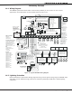
Expansion
13.1 Zone Expansion
Up to 574 re and burglary zones are available on the XR2500F using DMP Security Command keypad remote
zone capability and zone expansion modules. The panel keypad data bus supports up to sixteen supervised
device addresses with each address supporting up to four programmable expansion zones.
Up to 500 zones are available using the on-board LX-Bus along with additional expansion modules. Use the
461 Interface Adaptor, 462N, 462P, 462FM, or 481 interface cards, and any combination of sixteen, eight,
four, and single point zone expander modules and single point LX-Bus detectors.
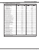
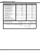
Combined current requirements of additional modules may require an additional 504-24 or 502-12 power
supply. See section Standby Battery Calculations when calculating power requirements.
Note: Do not use shielded wire for LX-Bus or Keypad Bus circuits.
13.2 Output Expansion
Note: Do not use shielded wire for LX-Bus or Keypad Bus circuits.
In addition to the two SPDT relays and four open collector outputs on the XR2500F, you can also connect up
to 25 Model 716 Output Expansion Modules to each LX-Bus. These modules can provide an additional 500
programmable SPDT relays.
The XR2500F provides 100 Output Schedules you can use for programming the 716 to perform a variety of
annunciation and control functions. You can also assign the 716 outputs to any panel Output Options such as
Fire Alarm, Communication Fail, or Phone Trouble Outputs. Refer to the 716 Installation Guide (LT-0183).
The LX-Bus™ also supports the Model 717 Graphic Annunciator Module. Each 717 module supplies 20
switched ground outputs that follow the state of their assigned zones.
Note: The 717 supports the rst eight keypad bus zones. To follow Keypad Bus zones nine through 16, install
multiple 716 modules. Refer to the 717 Installation Guide (LT-0235) and 716 Installation Guide (LT-0183).