
Installation guide

Digital Monitoring Products XR2500F Installation Guide
14
INSTALLATION
XR2500F Installation Guide Digital Monitoring Products
15
INSTALLATION
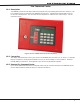
Panel Features
11.1 Description
The DMP XR2500F Command Processor™ Panel is a versatile 12 VDC, re communicator panel with battery
backup. The XR2500F provides eight on-board grounded zones for connecting Model 860, Class A zones and
two on-board 12 VDC Class B, Stye A powered zones. The powered zones have a reset capability to provide
for 2-wire smoke detectors, relays, or other latching devices. The XR2500F can communicate to one or two
DMP SCS-1/SCS-1R Receivers using digital dialer or network communication, or to non-DMP receivers using
the Contact ID format.
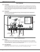
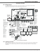
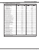
11.2 Connection
The XR2500F Command Processor panel is factory pre-wired and controls the other components in the
system. Refer to the wiring diagram below for wiring. See the following sections for descriptions of
additional XR2500F applications.
AC
1 2 3 4 5 6 7 8
10 11 12 13 14 15 16 17 18 199 20 21 22 23 24 25 26 27 28
+B BELL GND SMK GNDRED YEL GRN BLK Z1 Z2 Z3 Z4 Z5 Z6 Z7 Z8 Z9+ Z9– Z10+ Z10–AC –B GND GND GNDGND
K6 K7
Output 1 Output 2
J3
Phone Line
J10
J22
LX-Bus
Battery
Start
J23
J21
RS-232
Po
wer
LED
J8
PROG
J4
Tamper
J16
Reset
Out1 Out2
Outputs 3-6
J11
3
4
5
6
J2
J1
Ethernet
R
L
X
Link LED
Activity LED
OV
C
XR2500F
Command Processor™
Panel
Form C Relays (J2)
Output Color Code
Output 2 N/O Yellow
Output 2 Com White
Output 2 N/C Blue
Output 1 N/O Orange
Output 1 Com Gray
Output 1 N/C Violet
Annunciator Outputs (J11
)
Output Color Code
Output 3 Re
d
Output 4 Yellow
Output 5 Green
Output 6 Black
To 16 VAC
Tr
ansformer
Red wire to
positive terminal
of 12 VDC Battery
Black wire to
negative terminal
of 12 VDC Battery
To
866 Module
#2 terminal 1
(AUX PWR)
To Fire
Command
Center
To
504-24
DC -
To
866
Module #1
terminal 7
(BELL TRBL)
To 866 Module
#2 terminal 7
(BELL TRBL)
To
504-24
BATT TRBL
NC
To
504-24
AC TRBL
NC
To
893 J3 PANEL Connector
To
893 P10
Connector
To 866 Module
#1 terminal 3
(Alarm In)
To 866 Module
#2 terminal 3
(Alarm In)
J6
To LX-Bus
Modules
481 Zone Expansion Interface Card
Figure 11: XR2500F Panel Wiring
11.3 Relays
The XR2500F ships with two Model 305 Relays pre-installed to allow zone alarm control for the 866 NAC
Modules. When a re alarm occurs the bell output is factory programmed to turn on and provide power to
the contacts of the relays. Specic zone programming determines whether one or both relays turn on signal
voltage to the 866 NACs. This allows control of the NACs by zone.
11.4 Zone Reference
The XR2500F has been pre-wired in the factory. The rst 866 NAC module connects to Zone 1. The second
866 NAC module connects to Zone 2. Zones 3 and 4 connect to the 504-24 power supply.