
Installation guide

Digital Monitoring Products XR2500F Installation Guide
12
INTRODUCTION
XR2500F Installation Guide Digital Monitoring Products
13
INTRODUCTION
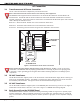
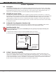
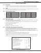
8.6 Connection
The 24 VDC power supply is completely pre-wired. Refer to the following 504-24 wiring diagram for specic
wire connections.
Figure 9: 504-24 Wiring
Interconnect Wiring Harness
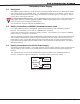
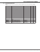
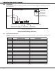
9.1 Interconnect Harness
This chart explains the wire colors on the Interconnect Wiring Harnesses. It also explains to what each wire
connects.
Wire Color Connection From Connection To
Red Panel Terminal 7 (DC Power) 866 Module #2 Terminal 1 (Auxiliary Power)
Black Panel Terminal 10 (Common) 504-24 DC - Negative DC Terminal (Ground)
Brown Panel Terminal 13 (Zone 1) 866 Module #1 Terminal 7 (Bell Trouble)
Violet Panel Terminal 15 (Zone 2) 866 Module #2 Terminal 7 (Bell Trouble)
Green Panel Terminal 16 (Zone 3) 504-24 Battery Trouble Terminal N/O
White Panel Terminal 18 (Zone 4) 504-24 AC Trouble Terminal N/C
Gray Panel J2 Pin 2 (Common) 866 Module #1 Terminal 3 (Alarm In)
Orange Panel J2 Pin 3 (Output 1 N/O) Panel Terminal #5 (Bell Output)
White Panel J2 Pin 5 (Common) 866 Module #2 Terminal 3 (Alarm In)
Yellow Panel J2 Pin 6 (Output 2 N/O) Panel Terminal #5 (Bell Output)
White/Red 504-24 DC + (Positive DC Terminal) 866 Module #2 Terminal 4 (Bell Power In)
Black 504-24 DC - (Negative DC Terminal) 866 Module #2 Terminal 2 (Ground)
Red 866 Module #2 Terminal 1 (Auxiliary Power) 866 Module #1 Terminal 1 (Auxiliary Power)
Black 866 Module #2 Terminal 2 (Ground) 866 Module #1 Terminal 2 (Ground)
Black 866 Module #2 Terminal 2 (Ground) 866 Module #1 Terminal 8 (Bell Trouble)
White/Red 866 Module #2 Terminal 4 (Bell Power In) 866 Module #1 Terminal 4 (Bell Power In)
Black 866 Module #2 Terminal 8 (Bell Trouble) 504-24 Battery Trouble Common Terminal
Black 866 Module #2 Terminal 8 (Bell Trouble) 866 Module #1 Terminal 8 (Bell Trouble)
Table 4: Interconnect Wiring Harness