
Installation guide

Digital Monitoring Products XR2500F Installation Guide
10
INTRODUCTION
XR2500F Installation Guide Digital Monitoring Products
11
INTRODUCTION
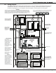
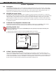
504-24 Power Supply
8.1 Description
The 504-24 is a power limited, switching power supply that meets UL, CSFM, NFPA, and FCC compliance
standards. Model 504-24 is rated for 24 VDC @ 4 Amps maximum and supplies power to the 866 Modules.
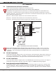
8.2 LEDs
The 504-24 has two status LEDs that show the current state of power. The green LED indicates low AC input.
The red LED indicates low standby battery power after AC has failed.
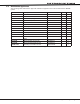
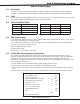
8.3 504-24 Condition Chart
Condition Voltage Levels LED Status Condition
AC Trouble Approximately. 102 VAC AC LED (Green) On AC Good
Battery Trouble Below 23.6 VDC AC LED (Green) Off AC Bad
Battery Restoral Above 25.0 VDC DC LED (Red) On Battery Good
Battery Cutoff Below 20.4 VDC DC LED (Red) Off Battery Bad
Table 2: 504-24 Condition and LED Indicators
8.4 504-24 UL Listings
For UL 603 Power Supplies for Burglary Alarm Systems and UL 294 Power Supplies for Access Control System
applications: Voltage Range of 22.9 to 25.5 VDC.
For UL 1481 Power Supplies for Fire Protective Signaling the following maximum battery standby Ampere
hours apply for 24 hours of battery backup:
Battery Standby Maximum: 49.2Ah
Output Voltage: 24 VDC
Output Current: 1.5A standby, 4 Amp alarm
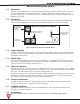
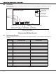
8.5 24 VDC NAC Standby Battery Calculations
The following calculation denes the total number of standby battery Amp-hours required to support
operation of the NACs and any other devices attached to the 504-24 power supply. From this calculation,
assemble the appropriate number of batteries that will just exceed the calculated total Amp-hour
requirement. The 866 NACs receive power for internal operation from the XR2500F panel and do not enter
in this calculation themselves.
1. Add all standby current values including the power supply operating current.
2. Multiply the total standby current by the number of standby hours needed.
3. Add all alarm current values from the notication appliances attached to the 866 NACs and multiply by
0.25.
4. Add the total alarm mA-hour with the total standby mA-hour and then multiply this number by 0.001.
Power Supply Operating Current 200 mA
Other Standby Current + ______ mA
1. Total Standby Current + ______ mA
Number of Standby Hours Required X ______ hr
2. Total Standby (mA-hr) Required = ______ mA-hr
3. Total Alarm Current = ______ mA
Total Alarm Current X 0.25 = ______ mA-hr
(0.25 = 5 minutes in alarm)
Total Standby (Required) + ______ mA-hr
Total = ______ mA-hr
X 0.001
4. Total Required Amp-hours = ______
Table 3: Battery Calculations