
Installation guide

Digital Monitoring Products XR2500F Installation Guide
8
INTRODUCTION
XR2500F Installation Guide Digital Monitoring Products
9
INTRODUCTION
LX-Bus™ Operation
6.1 Description
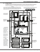
The XR2500F Command Processor™ panel supports LX-Bus operation directly from the panel. Each LX-Bus
circuit provides 100 additional zones. Use J22 LX-Bus Header for the rst 100 zones. Use the installed 481
Zone Expansion Interface Card for the next 100 zones. This provides a total of 200 expansion zones. To
install up to four additional Interface Cards use a Model 461 Interface Adaptor Card.
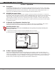
6.2 XR2500F On-board LX-Bus
To enable J22 to operate as an LX-Bus, place a jumper on the two pins next to the letter “L” on the J23
6-Pin header. When using J22 as an LX-Bus, connect a DMP Model 300 4-wire Harness to the J22 4-pin header
labeled LX-BUS. This provides the rst 100 LX-Bus zones numbered 500-599. Respect wire colors when
connecting devices and use all four wires. Reset the panel using J16 jumper to activate LX-Bus operation.
Note: Do NOT use shielded wire when using the LX-Bus. Do NOT connect the wires from the 4-wire harness
to the panel terminals.
6.3 LX-Bus 481 Zone Expansion Interface Card
The 481 Zone Expansion Interface Card provides an additional 100 zones to the XR2500F. When used in
conjunction with the on-board J22 LX-Bus the 481 LX-Bus zones are numbered 600 to 699.
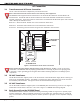
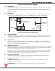
6.4 Installing the 481 Card
Remove AC and battery power from the XR2500F panel and ground yourself before handling and
installing the 481 Card.
1. Align the 481 Card 50 pin connector with the XR2500F panel J6 connector.
2. Press the 481 onto the J6 connector while applying even pressure to both sides.
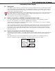
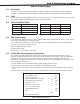
�
Figure 6: 481 Wiring
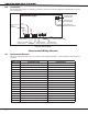
6.5 LX-Bus™ Expansion Capability
The on-board LX-Bus and the 481 Card each provide one 4-wire LX-Bus™ connection that allows you to
connect up to 100 Model 521LX, 521LXT, or SLRLX Addressable Smoke Detectors. Also each LX-Bus™ could
connect up to 25 Model 714, 715, and 725 Zone Expanders or 716 Output Expanders, up to six Model 714-16
or 715-16 Zone Expanders, and up to 100 Model 711 Zone Expanders. Power for the devices connected to
the 481 Card is provided through the expansion harness Black and Red wires.