
Installation guide

Digital Monitoring Products XR2500F Installation Guide
4
INTRODUCTION
XR2500F Installation Guide Digital Monitoring Products
5
INTRODUCTION
Secondary Power Supply
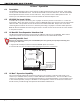
4.1 Description
The XR2500F system includes pre-wired cables for connecting a 24 VDC battery to the 504-24 power supply
and a 12 VDC battery to the XR2500F panel. For 24 VDC battery operation to the 504-24, connect two 12
VDC sealed lead-acid batteries in series using the included series connecting strap. See Figure 4. Observe
polarity when connecting all batteries.
Use sealed lead-acid batteries only. Use the DMP Model 367, 368, 369, 365, 366, 12 VDC sealed lead-acid
rechargeable batteries. Batteries supplied by DMP or manufactured by Eagle Picher or Yuasa have been
tested to ensure proper charging with DMP products.
Gel cell batteries cannot be used with the XR2500F panel.
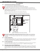
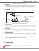
4.2 Battery Connection to XR2500F Command Processor panel
For 12 VDC battery operation to the XR2500F, connect the black battery lead to the battery negative
terminal. The black battery wire connects to XR2500F panel terminal 4.
Connect the red battery lead to the battery positive terminal. The red battery wire connects to XR2500F
panel terminal 3. See Figure 11 and Figure 2.
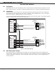
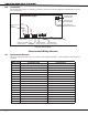
Add a second battery in parallel using the DMP Model 318 Dual Battery Harness. When wiring two batteries
with the Model 318 Dual Battery Harness, plug the Dual Battery Harness red male end into the panel red
female battery lead. Plug the Dual Battery Harness black male end into the panel black female battery
lead. Attach both Dual Wiring Harness female leads to the two batteries as described above. See Table 3:
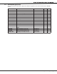
Battery Calculations.
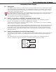
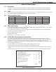
4.3 Battery Connection to the 504-24 Power Supply
The 504-24 is powered by 24 VDC. Two 12 VDC batteries connect together using the series connecting strap.
The black battery wire connects to the 24 VDC battery negative terminal and to the 504-24 negative AC
terminal.
The red battery wire connects to the 24 VDC battery positive terminal and to the 504-24 positive AC
terminal. See Figure 4, Figure 9, and Figure 2. Also see the Battery Information section.
Figure 4: 24 VDC Battery Wiring