
Installation guide

Digital Monitoring Products XR2500F Installation Guide
4
INTRODUCTION
XR2500F Installation Guide Digital Monitoring Products
5
INTRODUCTION
AC Connection
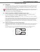
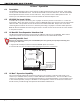
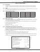
3.1 Transformers and AC Power Connection
The AC connection should be completed by a licensed electrician.
Never share the Fire Alarm Control Panel circuit with any other equipment.
The XR2500F comes supplied with two transformers: the 16 VAC 56 VA transformer and the 28 VAC 175
VA transformer. The 28 VAC and the 16 VAC transformer white leads and black leads must be connected
together respectively. These wires must be connected to an unswitched 120 VAC 60 Hz power source with at
least 1.85 Amps of available current.
Black wire - attach the black 120 VAC wire to the transformer black wires.
White wire - attach the white 120 VAC wire to the transformer white wires.
Green wire - attach the green wire lead to the green wire attached to the enclosure.
Figure 3: Transformers and AC Power Connection
Always ground the panel before applying power to any devices! Use 18 AWG or larger for all power
connections. The XR2500F must be properly grounded before connecting any devices or applying power
to the panel. Proper grounding protects against Electrostatic Discharge (ESD) that can damage system
components.
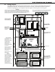
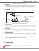
3.2 28 VAC Transformer
The 28 VAC Transformer supplies power to the AC terminals of the 504-24 Power Supply which is factory pre-
wired to the two 866 NAC modules. The 28 VAC is located in the upper right hand corner of the enclosure
surrounded by a metal divider. See Figure 3 above and the 504-24 Power Supply section.
3.3 16 VAC Transformer
The 16 VAC 56 VA transformer supplies power to the XR2500F panel and is factory pre-wired. See Figure 3:
Transformers and AC Power Connection. Also refer to Figure 11: XR2500F Panel Wiring Diagram.
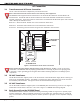
3.4 Earth Ground from the XR2500F Panel
The XR2500F terminal 4 must be connected to earth ground using 14 AWG or larger wire to provide proper
transient suppression. DMP recommends connecting to a cold water pipe, building ground, or ground rod
only. Do not connect to an electrical ground or conduit, sprinkler or gas pipes, or to a telephone company
ground.