
Installation guide

Digital Monitoring Products XR2500F Installation Guide
2
INTRODUCTION
XR2500F Installation Guide Digital Monitoring Products
3
INTRODUCTION
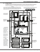
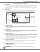
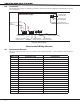
2.6 Wiring Diagram
The XR2500F system below shows the component layout. The wires shown in this guide have been factory
installed and connected. The dashed lines represent wires running underneath or behind a component.
Detailed wiring diagrams for each supplied component appear in following sections of this guide.
Figure 2: XR2500F System