
Installation guide

Digital Monitoring Products XR2500F Installation Guide
2
INTRODUCTION
XR2500F Installation Guide Digital Monitoring Products
3
INTRODUCTION
Mounting
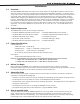
2.1 Mounting the Enclosure
The XR2500F must be mounted in a secure,
dry location to protect the unit from damage
due to tampering and the elements. The
enclosure can be either ush mounted or
surface mounted and includes a hinged door
with lock. The hole in the enclosure door
allows access to the Fire Command Center
without opening the door. Figure 1 illustrates
the mounting hole locations for the panel
enclosure.
The enclosure dimensions are 32” tall, 14.5”
wide, by 4” deep. The lid adds about 0.5” to
each side.
2.2 Surface Mounting
The enclosure center hole should be attached
to a wall stud. Due to the enclosure weight,
especially the batteries, it is extremely
important to mount the enclosure on the
stud. Attach the two holes beside the center
hole to sheetrock to secure enclosure. When
mounting the enclosure, be sure to leave
room for the panel door to swing open. The
door lock should be easily accessible.
2.3 Flush Mounting
The enclosure can also be ush mounted. Use
1” screws to secure the enclosure between
two studs using the two sets of holes on
the sides of the enclosure. Use the top and
bottom holes to secure to horizontal studs, if
necessary.
2.4 Fire Command Center LCD
Keyboard
A Fire Command Center LCD Keyboard
has been factory installed on the XR2500F
enclosure. A keyswitch has also been
installed and pre-wired to the left of the
keyboard. The user can turn the keyswitch to
enable the four function keys without opening
the enclosure door.
2.5 Metal Backplate
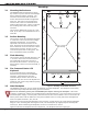
The XR2500F components are pre-wired and installed on a metal backplate. The backplate can be easily
removed to keep components safe during pre-wire activities.
Remove AC and battery power from the XR2500F panel before removing the backplate. Disconnect
all battery, transformer, and the Fire Command Center LCD keyboard wires. Also remove the AC wires from
the 504-24 power supply. From the panel, disconnect the AC wires from terminals 1 and 2. Disconnect the
battery wires either from the batteries or the panel terminals 3 and 4. Finally, disconnect the keyboard
wires from panel terminals 7, 8, 9, and 10.
Remove the screws securing the backplate to the enclosure. Loosen the two top screws that the backplate
hangs on. After loosening and removing the screws, lift the backplate up slightly and pull the backplate
toward you. When reinstalling the backplate, be sure all connections are secure.
Figure 2 illustrates the backplate and the components. The backplate is shown in light gray.
Figure 1: Mounting the XR2500F Enclosure