INSTALLATION GUIDE XR2500F ADDRESSABLE FIRE ALARM CONTROL PANEL
MODEL XR2500F COMMAND PROCESSOR INSTALLATION GUIDE FCC NOTICE This equipment generates and uses radio frequency energy and, if not installed and used properly in strict accordance with the manufacturer’s instructions, may cause interference with radio and television reception.
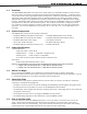
TABLE OF CONTENTS Revisions to This Document Introduction 1.1 1.2 1.3 1.4 1.5 1.6 Overview ...................................................................................................... 1 System Components ...................................................................................... 1 Power Specifications ...................................................................................... 1 Before You Begin .................................................................................
TABLE OF CONTENTS Interconnect Wiring Harness 9.1 Interconnect Harness................................................................................... 12 Fire Command Center 10.1 10.2 10.3 Description.................................................................................................. 13 Connection.................................................................................................. 13 Remote Fire Command Center .................................................................
TABLE OF CONTENTS Powered Zones for 2-Wire Smoke Detectors 19.1 19.2 Terminals 25–26 and 27–28 ......................................................................... 25 Compatible 2-Wire Smoke Detector Chart...................................................... 26 Protection Zones 20.1 20.2 20.3 20.4 Terminals 13–24 .......................................................................................... 27 Operational Parameters........................................................................
TABLE OF CONTENTS UL 1635 Specifications 31.1 31.2 31.3 31.4 31.5 31.6 System Trouble Display ................................................................................ 33 Digital Dialer Telephone Number................................................................... 33 Test Time.................................................................................................... 33 Closing Wait ................................................................................................
TABLE OF CONTENTS California State Fire Marshal Specifications 38.1 Bell Output Definition................................................................................... 38 New York City (MEA) Specifications 39.1 39.2 39.3 39.4 39.5 Introduction ................................................................................................ 38 Digital Dialer and Network Communication .................................................... 38 Wiring .......................................................
REVISIONS Revisions to This Document This section explains the changes made to this document during this revision. It lists the date and identifies the change(s) made, the related section number and section heading, and a summary of the change. Date Section Number and Heading 10/05 2.6 Wiring Diagram 6.5 LX-Bus Expansion 12.6 Outputs 13.2 Output Expansion 14.1 Wiring Diagram 14.3 Accessory Devices 14.4 Mounting Keypads 14.5 Connecting Bus Devices 15.7 Standby Battery Calculations 15.
INTRODUCTION Introduction 1.1 Overview The DMP XR2500F Addressable Fire Alarm Control Panel (FACP) is an expandable 24 VDC Fire Alarm Control with built-in DACT and LCD Fire Command Center keyboard with membrane keyswitch. A complete system can provide a total of 574 programmable inputs and outputs for commercial and industrial fire alarm service. The 24 VDC 4 Amp notification appliance power is distributed between two class B style W NAC outputs.
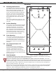
INTRODUCTION Mounting 2.1 Mounting the Enclosure The XR2500F must be mounted in a secure, dry location to protect the unit from damage due to tampering and the elements. The enclosure can be either flush mounted or surface mounted and includes a hinged door with lock. The hole in the enclosure door allows access to the Fire Command Center without opening the door. Figure 1 illustrates the mounting hole locations for the panel enclosure.
INTRODUCTION 2.6 Wiring Diagram The XR2500F system below shows the component layout. The wires shown in this guide have been factory installed and connected. The dashed lines represent wires running underneath or behind a component. Detailed wiring diagrams for each supplied component appear in following sections of this guide.
INTRODUCTION AC Connection 3.1 Transformers and AC Power Connection The AC connection should be completed by a licensed electrician. Never share the Fire Alarm Control Panel circuit with any other equipment. The XR2500F comes supplied with two transformers: the 16 VAC 56 VA transformer and the 28 VAC 175 VA transformer. The 28 VAC and the 16 VAC transformer white leads and black leads must be connected together respectively.
INTRODUCTION Secondary Power Supply 4.1 Description The XR2500F system includes pre-wired cables for connecting a 24 VDC battery to the 504-24 power supply and a 12 VDC battery to the XR2500F panel. For 24 VDC battery operation to the 504-24, connect two 12 VDC sealed lead-acid batteries in series using the included series connecting strap. See Figure 4. Observe polarity when connecting all batteries. Use sealed lead-acid batteries only.
INTRODUCTION Two 866 NAC Modules 5.1 Description Each 866 provides one style W indicating circuit for supervising UL polarized notification appliances, such as bells, strobes, and horns. See Table 1: Notification Appliances for a list of approved notification appliances. 5.2 Connection Each 866 module is pre-installed on the removable backplate using the standard three-hole configuration. The modules are factory pre-wired to each other, the 504-24, and the XR2500F panel.
INTRODUCTION 5.4 Notification Appliances The following table indicates the approved notification appliances that can be used with the XR2500F system. DMP Part Number Description Wheelock Model No.
INTRODUCTION LX-Bus™ Operation 6.1 Description The XR2500F Command Processor™ panel supports LX-Bus operation directly from the panel. Each LX-Bus circuit provides 100 additional zones. Use J22 LX-Bus Header for the first 100 zones. Use the installed 481 Zone Expansion Interface Card for the next 100 zones. This provides a total of 200 expansion zones. To install up to four additional Interface Cards use a Model 461 Interface Adaptor Card. 6.
INTRODUCTION 893A Dual Phone Line Module 7.1 Description The 893A is a dual telephone line supervision module that allows the panel to indicate a phone line failure to the premises and the central monitoring station. After the 893A senses a failure on the main line, it switches to the backup, or secondary, phone line. The 893A installs on the removable backplate above the XR2500F circuit board. 7.
INTRODUCTION 7.9 Notification The user must not repair registered terminal equipment. In case of trouble, immediately unplug the device from the telephone jack. The factory warranty provides for repairs. Registered terminal equipment may not be used on party lines or in connection with coin telephones. Notify the telephone company with the following information: a. The particular line(s) where the service is connected b. The FCC registration number as listed in Section 7.5 c. The ringer equivalence d.
INTRODUCTION 504-24 Power Supply 8.1 Description The 504-24 is a power limited, switching power supply that meets UL, CSFM, NFPA, and FCC compliance standards. Model 504-24 is rated for 24 VDC @ 4 Amps maximum and supplies power to the 866 Modules. 8.2 LEDs The 504-24 has two status LEDs that show the current state of power. The green LED indicates low AC input. The red LED indicates low standby battery power after AC has failed. 8.
INTRODUCTION 8.6 Connection The 24 VDC power supply is completely pre-wired. Refer to the following 504-24 wiring diagram for specific wire connections.
INTRODUCTION Fire Command Center 10.1 Description The XR2500F provides an LCD display and 20-key keyboard for programming and system user operation. The Fire Command Center is installed on the XR2500F enclosure door. A keyswitch is installed and pre-wired to the left of the keyboard. The user must turn the keyswitch to enable the four function keys. See the illustration below. Figure 10: Fire Command Center LCD and Keyboard 10.
INSTALLATION Panel Features 11.1 Description The DMP XR2500F Command Processor™ Panel is a versatile 12 VDC, fire communicator panel with battery backup. The XR2500F provides eight on-board grounded zones for connecting Model 860, Class A zones and two on-board 12 VDC Class B, Stye A powered zones. The powered zones have a reset capability to provide for 2-wire smoke detectors, relays, or other latching devices.
INSTALLATION XR2500F Product Specifications 12.1 Power Supply Transformer Input: Primary input: 120 VAC, 60 Hz, Secondary output: 16 VAC 56 VA Standby Battery: 12 VDC, 1.0 Amps Max. charging current Auxiliary: 12 VDC output at 1.5 Amp Max Bell Output: 12 VDC at 1.5 Amp Max Note: The combined Auxiliary and Bell outputs total cannot exceed 3 Amps with a 56 VA Transformer. All circuits are inherent Power Limited except the red battery wire and AC terminal.
INSTALLATION Expansion 13.1 Zone Expansion Up to 574 fire and burglary zones are available on the XR2500F using DMP Security Command keypad remote zone capability and zone expansion modules. The panel keypad data bus supports up to sixteen supervised device addresses with each address supporting up to four programmable expansion zones. Up to 500 zones are available using the on-board LX-Bus along with additional expansion modules.
INSTALLATION Accessory Devices 14.1 Wiring Diagram The XR2500F system below shows some of the accessory modules you can connect for use in various applications. A brief description of each module follows in section 14.3. s s J4 Tamper Wiring on terminals 5 through 22 must exit right and maintain 1/4" separation from the AC and battery positive wiring.
INSTALLATION 14.3 Accessory Devices Interface Adaptor and Interface Cards 461 Interface Adaptor Card Allows you to connect two or more expansion interface cards to the XR2500F panel. The 461 is an expansion board that plugs into the panel J6 Interface Connector and is required when using two or more Interface Cards. Use combinations of Interface Cards for expanding zones, network interfacing, and local printing.
INSTALLATION 14.4 Mounting Keypads and Zone Expansion Modules LCD keypads have removable covers that allow you to easily mount the keypad to a wall or other flat surface using the screw holes on each corner of the base. Before mounting the base, connect the keypad wire harness leads to the keypad cable from the panel and to any device wiring run to that location.
INSTALLATION Battery Information 15.1 Battery Only Restart When powering up the XR2500F panel without AC power, briefly short across the battery start pads to pull in the battery cutoff relay. The leads need a momentary short only. Once the relay has pulled in, the battery voltage holds it in that condition. If the XR2500F panel is powered up with an AC transformer, the battery cutoff relay is pulled in automatically. For battery start pad location refer to Figure 11. 15.
INSTALLATION 15.7 XR2500F Standby Battery Calculations Standby Battery Power Calculations Standby Current XR2500F Control Panel Relay Outputs 1-2 (ON) Switch Grounds 3-6 (ON) Active Zones 1-8 Active Zones 9-10 2-Wire Smoke Detectors Panel Bell Output Qty Qty Qty Qty Qty Qty ___ 1_ ______ ______ ______ ______ ______ x x x x x x 893A Dual Phone Line Module Qty ______ x 461 Interface Adaptor Card 180mA 30mA 5mA 1.6mA 4mA 0.
INSTALLATION Standby Battery Power Calculations 736P POPIT Interface Module Radionics Popex, POPITs, OctoPOPITs 710 Bus Splitter/Repeater Module 710F Fire Bus Splitter/Repeater Module 711, 714 Zone Expansion Modules Active Zones (EOL Installed) 712-8 Zone Expansion Module Active Zones (EOL Installed) 714-8, 714-16 Zone Expansion Module Active Zones (EOL Installed) 715 Zone Expansion Module Active Zones (EOL Installed) 2-Wire Smokes 715-8, 715-16 Zone Expansion Modules Active Zones (EOL Installed) 2-Wire Smo
INSTALLATION 15.8 Standby Battery Selection To choose the type and number of batteries needed for 24, 60, or 72 hours of standby power based on the Amp Hours Required calculation from section 6.8 XR500 Series Power Requirements, perform the following: 1. Select the desired standby hours required from the table below: 24, 60, or 72 hours 2. Select the desired battery size: Model 368 (12 VDC 4.5 Ah), Model 369 (12 VDC 7 Ah), Model 367 (12 VDC 7.7 Ah), Model 365 (12 VDC 9 Ah), Model 366 (12 VDC 18 Ah). 3.
INSTALLATION Bell Output 16.1 Terminals 5 and 6 Terminal 5 supplies positive 12 VDC to power alarm bells or horns. This output can be steady, pulsed, or temporal depending upon the Bell Action specified in Output Options. Terminal 6 is the ground reference for the bell circuit. This supervised output detects 10k Ohms or less as normal. The indicating appliance can supply this resistance.
INSTALLATION Smoke and Glassbreak Detector Output 18.1 Terminals 11 and 12 Terminal 11 supplies positive 12 VDC to power 4-wire smoke detectors and other powered devices. This output can be turned off by the user for five seconds using the Sensor Reset User Menu option to allow latched devices to reset. Terminal 12 is the ground reference for terminal 11. See LT-0164 for a list of approved 4-wire smoke detectors and power supervision relays. 18.
INSTALLATION 19.2 Compatible 2-Wire Smoke Detector Chart Manufacturer Model Detector ID Base Detection Systems DS230, DS230F B/A MB2W, MB2WL A 8.5-33 10 Detection Systems DS250, DS250TH B MB2W, MB2WL A 8.5-33 10/12 Detection Systems DS250HD B MB2W, MB2WL A 8.5-33 10 B/A MB2W, MB2WL A 8.5-33 17 8.
INSTALLATION Protection Zones 20.1 Terminals 13–24 Zones 1 to 8 (terminals 13 to 24) on the XR2500F panel are all grounded burglary zones. For programming purposes, the zone numbers are 1 through 8. Listed below are terminal 13 to 24 connection functions.
INSTALLATION Dry Contact Relay Outputs 21.1 Description The XR2500F panel provides two auxiliary SPDT relays with the two DMP Model 305 relays in K6 (Output 1) and K7 (Output 2) and a Model 431 Output Harness on the J2 6-pin Header.
INSTALLATION J11 Annunciator Outputs 22.1 Description The four annunciator outputs can be programmed to indicate the activity of the panel zones or conditions occurring on the system. Annunciator outputs do not provide a voltage but instead switch-to-ground a voltage from another source. The outputs can respond to any of the conditions listed in section 22.1. 22.2 Model 300 Harness Wiring Access the open collector outputs by installing DMP 300 Harness on the 4-pin header labeled J11.
INSTALLATION J22 LX-Bus Expansion Connector 24.1 Description J22 LX-Bus and J21 RS-232 connectors cannot be used at the same time. Either use J21 to connect a serial device for PC Log Reporting, or use J22 to connect an LX-Bus device. This is determined by where you install the jumper on J23 6-Pin Header. Reset the panel using J16 jumper to activate selected J23 operation. Note: Do NOT use shielded wire when using the LX-Bus. Do NOT connect the wires from the 4-wire harness to the panel terminals. 24.
INSTALLATION J1 Ethernet Connector 26.1 Description The J1 Ethernet Connector is available to connect directly to an Ethernet network using a standard patch cable. J1 Ethernet Link LED Activity LED Figure 15: J1 Header and LEDs 26.2 Ethernet LEDs The two LEDs, located to the left of J1 Ethernet Connector, indicate network operation. The top, Activity LED flashes green to indicate the network traffic is good. The bottom, Link LED flashes yellow to indicate messages are being sent and received.
COMPLIANCE Universal UL Burglary Specifications 28.1 Introduction The programming and installation specifications contained in this section must be completed when installing the XR2500F panel in accordance with any of the UL burglary standards. Additional specifications may be required by a particular standard. 28.2 Wiring All wiring must be in accordance with NEC, ANSI/NFPA 70, UL 681. All transformer wires must be installed in conduit. 28.
COMPLIANCE UL 1023 Specifications Household Burglar-Alarm System Units 30.1 Audible Devices At least one listed audible device (Ademco AB12M) rated to operate over the voltage rate of 11.7 VDC to 12.8 VDC and rated at 85 DB minimum must be used. 30.2 Auxiliary Circuits At least one burglary alarm initiating device shall be used on the system. If the voltage for the device is applied by the control unit the burglary alarm initiating device shall be rated to operate over the range of 11.5 VDC to 12.7 VDC.
COMPLIANCE UL 1610 AND 1076 Specifications Central-Station and Proprietary Burglar-Alarm Units 32.1 Opening/Closing Reports The Opening/Closing Reports option must be programmed as YES. See the XR500 Series Programming Guide (LT-0679). 32.2 Closing Wait The Closing Wait option must be programmed YES. See the XR500 Series Programming Guide (LT-0679). 32.3 Entry Delay The maximum entry delay used must not be more than 60 seconds. See the XR500 Series Programming Guide (LT-0679). 32.
COMPLIANCE UL 365 and 609 Specifications Police Station Connected and Local Burglar Alarm Units and Systems 33.1 System Trouble Display The Status List Display must include at least one keypad that displays system monitor troubles. See the XR500 Series Programming Guide (LT-0679). 33.2 Entry Delay The maximum entry delay used must not be more than 60 seconds. See the XR500 Series Programing Guide (LT-0679). 33.3 Exit Delay The maximum exit delay used must not be more than 60 seconds.
COMPLIANCE Universal UL and NFPA Fire Alarm Specifications 35.1 Introduction The programming and installation specifications contained in this section must be completed when installing the Model XR2500F in accordance with any of the UL or NFPA fire standards. Additional specifications may be required by a particular standard. 35.2 Wiring All wiring must be in accordance with NEC, ANSI/NFPA 70. 35.3 Transformer A wire-in transformer should be used. Use the supplied 16 VAC 56 VA transformer.
COMPLIANCE UL 864 NFPA 72 (Chapter 9) Specifications Control Units for Fire-Protective Signaling Systems 36.1 Zone Restoral Reports The Restoral Reports option must be selected as YES or Disarm. See the XR500 Series Programming Guide (LT-0679). 36.2 Power Fail Delay The Power Fail Delay option must be selected as required by the service of the panel. For Central Station service: 6-12, for Remote Station service: 12-15. See the XR500 Series Programming Guide (LT-0679). 36.
COMPLIANCE UL 985 NFPA 72 (Chapter 2) Specifications Household Fire Warning System Units 37.1 Bell Output Definition The Model XR2500F panel Bell Output must be programmed to operate steady on burglary alarms and pulsed or temporal on fire alarms. See the XR500 Series Programming Guide (LT-0679). 37.2 Audible Devices At least one listed audible device rated to operate over the voltage rate of 11.7 VDC to 12.8 VDC and rated at 85 DB minimum must be used. 37.
XR2500F Installation Guide ���� ���������� ������ ������ ��������������������������� ������������� ������������ ��������� ����� ���������� ��������������� ��������������� �������������� �������������� �������������� �������������� ��������������� ��������������� ���� ������ ��������������������� ��������������������� ������������ ��������� ���� ������� ��������� ����� ���������� ������������� ������������ ������������ �������������� �������������� ���� ������ ��������������������� ���������������
COMPLIANCE �� ������ �� �������� ������������������� ����� ��� ���������� ����� ���������� ��������� �� ��� ����������������� ����������������������������������� �������������������������������������� ��� � � � ������������������������������������������ ���������� ��������������������������������������� ��������������������������������������� ��������������������������������� ��� �� �� �� �� �� ���� ��� ��� ��� ��� ��� ��� ��� �� ��� �� � � � � � � � � � � �� �������������������� �����
WIRING DIAGRAMS �� ������ �� ��� ���������� ����� ���������� ��������� �������� ������������������� ����� �� ��� ��� ������ � � � ��� �� ��� �������� ����� �� �� ��� ��� ����� �� �� �� �� �� ���� ��� ��� ��� ��� ��� ��� ��� �� ��� �� ������������������������������ ������������� ������������������������ �������� � � � � � � ��������������������������������� 40.
WIRING DIAGRAMS �������� ������������������� ����� �� ������ �� ��� ���������� ����� ���������� ��������� �� ��� ����������������� ����������������������������������� ����������������������������������� ������ ��� �� � �� �� � �� ����� ����� �� �� �� �� �� �� ���� ��� ��� ��� ��� ��� ��� ��� �� ��� �� � � � � � � � � � �� ��������� �������������� �� ��� �������� ����� �� �� �� �� ��� �� �� �� � ����������� ��� � � � ��� ����� �� ��� �� �� ��� �� �� �� �� �� �� �� ������
WIRING DIAGRAMS 40.
Digital Monitoring Products 44 ��������� ����� ���������� ������������� ������������ ������������ �������������� �������������� ���� ������ ��������������������� ������ � ������ � ��������������������������� ������������� ������������ ��������� ����� ���������� ������������� ������������ ������������ �������������� �������������� ���� ������ ��������������������� ������� ������� ������������� ������� � � � � ������� ������������� � � ������ ��� � ��� �������� ������������ �� ���� ���
WIRING DIAGRAMS �������� ������������������� ����� �� ������ �� ��� ���������� ����� ���������� ��������� �� ����������������� ����������������������������������� ����������������������������������� ��� ��� ������ � � � ��� �� ��� �������� ����� �� �� �� �� �� �� ���� ��� ��� ��� ��� ��� ��� ��� �� ��� �� ������������������ ������������������ � � � � � � � � � �� �� �� �� �� ��� ��� ����� �� ��� �� �� ��� �� �� �� �� �� �� �� �� ��� �� ��� ��� �������� �� �� �� �� ��
WIRING DIAGRAMS 40.
XR2500F Installation Guide �� � � � ��� ��� ��� ������ ��� �� �� ������ �� �� � � � � � � � � � �� �� �� �� �� �� �� ��� ��� �� �� �� �� ��� ����� �� �� �� �� �� �� ������ ������� �������� ��� ��� ��� �� � �� � � � � ������� � ��������� ��������� ��������� �������� ��������� ������������ ��������������������� ������������������������� ��������������������������������� ���� ���������� ������ ������ ��� ������ ��� ������������������������������������������������
OPERATING INSTRUCTIONS MODEL XR2500F PANELS NORMAL STANDBY CONDITION When the system is in the normal standby condition, the keypad shows either the time of day or a blank display. ALARM CONDITION When the system is in an alarm condition, the keypad display shows the violated zone name(s) followed by an alarm display. ALARM SILENCE To silence the alarm while the bell or siren is sounding, enter your code number and press the COMMAND key.