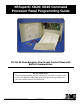
XRSuper6/XR20/XR40 Command Processor Panel Programming Guide 22/26/42 Zone Burglary/Fire/Access Control Panel with Built-in Communicator Do Not Throw Away! This programming guide contains information you need to program and service the XRSuper6/XR20/XR40 panel and should be kept along with your other DMP technical documentation. 2500 N. Partnership Boulevard Springfield, MO 65803 www.dmpnet.
MODEL XRSuper6/XR20/XR40 PROGRAMMING GUIDE When using the Series XRSuper6/XR20/XR40 control for any UL, NFPA, CSFM or other listing organization's approved methods, refer to this manual and the XRSuper6/XR20/ XR40 Installation Guide (LT-0624). These documents outline the installation and programming requirements of all applications for which the XRSuper6/XR20/XR40 is approved. Copyright © 1996 - 2001 Digital Monitoring Products, Inc. Information furnished by DMP is believed to be accurate and reliable.
TABLE OF CONTENTS Section Page 1.1 Before You Begin ........................................................................................ 1 1.2 Getting Started .......................................................................................... 1 1.3 Programming Menu ..................................................................................... 2 1.4 Programmer Lockout Codes ........................................................................... 2 1.5 Reset Timeout ...........
TABLE OF CONTENTS Section ii Page 4.1 REMOTE OPTIONS ...................................................................................... 10 4.2 REMOTE KEY ............................................................................................ 10 4.3 MANUFACTURER AUTHORIZATION .................................................................... 10 4.4 ARMED RINGS ........................................................................................... 10 4.5 DISARMED RINGS .............
TABLE OF CONTENTS Section Page 7.5C COMMUNICATION FAILURE OUTPUT .................................................................. 17 7.5D FIRE ALARM OUTPUT ................................................................................... 17 7.5E FIRE TROUBLE OUTPUT ............................................................................... 17 7.5F AMBUSH OUTPUT ....................................................................................... 17 7.5G ENTRY OUTPUT ....................
TABLE OF CONTENTS Section iv Page 12.3 False Alarm Reduction Features ..................................................................... 28 12.4 4-2 reporting operation ............................................................................... 28 12.5 Zone type descriptions ................................................................................ 29 12.6 Manual telephone line seizure ....................................................................... 29 12.
INTRODUCTION 1-INTRODUCTION Introduction 1.1 Before You Begin About this Manual This manual provides programming information for the DMP XRSuper6/XR20/XR40 Command Processor Panels. After this Introduction, the remaining sections describe the functions of each programming menu items along with their available options. The XRSuper6/XR20/XR40 contains all of its programming information in an on-board processor and does not require an external programmer.
INTRODUCTION 1.3 Programming Menu You are now ready to start programming the XRSuper6/XR20/XR40 panel. Pressing the COMMAND key scrolls you through the 10 programming menu items listed in below. Note: The 692 Security Command keypad is not suitable for panel programming.
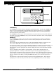
INTRODUCTION 1.6 Special Keys P O A W R E M E R D JONES RESIDENCE F R I 2 : 51 AM Select Keys 1 ABC 5 MNO 9 2 3 D EF GH I 6 7 P Q R STU 0 4 JKL 8 V WX COMMAND YZ COMMAND Key ARROW Key Figure 1: Keypad Function keys COMMAND Key The COMMAND key is used to advance through the programming options. Pressing the COMMAND key allows you to go forward through the programming menu and through each step of a programming section.
INTRODUCTION 1.7 Entering Alpha Characters Some options during programming require you to enter alpha characters. To enter an alpha character, press the digit key that has that letter written below it. The keypad displays the number digit of the key. Press the Select key that corresponds to the location of the letter under the key. Pressing a different Select key changes the letter. When another digit key is pressed, the last letter displayed is retained and the process is started over.
INITIALIZATION 2.1 INITIALIZATION This function allows you to set the panel's programmed memory back to the factory defaults in preparation for system programming. INITIALIZATION SURE? YES NO After you select YES to clear a section of memory, the panel asks if you are sure you want to clear the memory. This is a safeguard against accidently erasing part of your programming. No memory is cleared from the programming until you answer yes to the SURE? YES NO prompt.
COMMUNICATION 3.1 3.2 COMMUNICATION COMM TYPE: NONE NONE DD 4-2 M2E CID 3.3 3.4 ACCOUNT NO:12345 XMIT DELAY: 00 COMMUNICATION The Communication section allows you to configure the communication settings for the XRSuper6/XR20/XR40 panel. After choosing the Communication Type, continue through the list of options. COMMUNICATION TYPE This specifies the communication method the panel uses to contact the receiver.
COMMUNICATION 3.7 EVENT MGR: SEND SND DLY KEEP EVENT MANAGER This option specifies when non-alarm reports are sent to the receiver. This selection does not affect zone alarm, zone trouble, zone restoral, supervisory, or serviceman messages. Closing reports are not delayed if you have programmed a YES for the Bell Test option. SND - All reports are sent to the receiver as they occur.
COMMUNICATION 3.16 FIRST PHONE NO. – – 3.17 SECOND PHONE NO. – – FIRST TELEPHONE NUMBER This is the first number the panel dials when sending reports to this receiver. A phone number can consist of two lines of 16 characters in length to equal 32 characters. You can program a three-second pause in the dialing sequence by entering the letter P. You can program a dial tone detect by entering the letter D. These characters are counted as part of the allowable 32 characters.
COMMUNICATION 3.24 BACKUP NO 3.25 FIRST PHONE NO. – – 3.26 SECOND PHONE NO. – – BACKUP REPORTING YES enables this receiver to be a backup to the other receiver in the event the other receiver cannot be contacted. FIRST TELEPHONE NUMBER This is the first number the panel dials when sending reports to this receiver. A phone number can consist of two lines of 16 characters in length to equal 32 characters. You can program a three second pause in the dialing sequence by entering the letter P.
REMOTE OPTIONS 4.1 REMOTE OPTIONS REMOTE OPTIONS This section allows you to enter the information needed for Remote Command/ Remote Programming operation. A description of the Remote Options follow: 4.2 RMT KEY: REMOTE KEY This option allows you to enter a code of up to eight digits for use in verifying the authority of an alarm or service receiver to perform a remote command/ programming session. The receiver must give the correct key to the panel before being allowed access.
REMOTE OPTIONS 4.7 SVC RCVR YES SERVICE RECEIVER AUTHORIZATION YES enables remote commands and programming to be accepted from a secondary service receiver other than the alarm SCS-1 Receiver. The Remote Key option can also be required. With YES selected, the panel requests the service receiver key the first time it is contacted by the service receiver. The panel retains this service receiver key in memory and accepts remote commands from the service receiver.
SYSTEM REPORTS 5.1 SYSTEM REPORTS 5.2 OPN/CLOS NO NO YES LTD ALM 5.3 ABORT NO YES YES DISARM 5.5 BYPASS OPENING/CLOSING REPORTS This option allows the selection of Opening/Closing Reports and the number of reports sent to the receiver. NO - Opening/Closing Reports are not sent by the panel. YES - The panel will send Opening/Closing Reports for each programmed area. LTD - The panel sends only one opening and one closing report.
SYSTEM OPTIONS 6.1 6.2 SYSTEM OPTIONS This section allows you to select system wide parameters used in the operation of the XRSuper6/XR20/XR40 system. A description of each System Option follows: SYSTEM OPTIONS MODE: ALL/ PERIM AREA A / P H / A MODE This configures the panel as either a four Area system (XR20/XR40 only), an All/ Perimeter system (Perimeter/Interior), or a Home/Away system (Perimeter, Interior, and Bedrooms). Zones must be assigned to Bedrooms for the area to be active. 6.
SYSTEM OPTIONS 6.9 RST SBYP YES RESET SWINGER BYPASS When YES is selected, a swinger bypassed zone is reset if it remains in a normal condition for one hour after being bypassed. A report of the automatic reset is sent to the receiver if Bypass Reports has been selected as YES. See the BYPASS REPORTS section. 6.10 PHON ACC NO TELEPHONE ACCESS YES allows the use of standard DTMF telephones to arm and disarm and check the armed status of the XRSuper6/XR20/XR40 panel.
SYSTEM OPTIONS 6.13 TIME CHG HRS FROM GMT: YES 6 TIME ZONE CHANGES This function allows the panel to request automatic time changes from the DMP SCS1 receiver. For the receiver to send time changes, it must be programmed to send time changes and must be receiving time change updates from the host automation computer at least every 24 hours. Default is YES. When time zone is programmed YES, enter the number (0-23) that indicates the Greenwich Time zone (GMT) where the panel is located. The default is 6.
OUTPUT OPTIONS 7.1 OUTPUT OPTIONS OUTPUT OPTIONS This function allows you to program Bell Output functions and certain Output options. Switched Ground (open collector) outputs are available using the 4-wire output harness on the XRSuper6/XR20/XR40 board. Refer to the XRSuper6/XR20/ XR40 Installation Guide (LT-0624) for complete information. A description of each output option follows. 7.2 BELL CUTOFF: BELL CUTOFF TIME Enter the maximum time the Bell Output remains on.
OUTPUT OPTIONS 7.5 OUTPUT ACTION . . . 7.5A CO OUTS: - - - - 7.5B CUTOFF TIME: OUTPUT ACTION This option allows you to define the operation of the four on-board annunciator outputs. CUTOFF OUTPUTS Any or all of the available outputs can be programmed here to turn off after the time specified in OUTPUT CUTOFF TIME. See section OUTPUT CUTOFF TIME. To disable this option, press any Select key to clear the display of output numbers and then press COMMAND.
OUTPUT OPTIONS 7.5L GND STRT OUT: 0 GROUND START OUTPUT This output is turned on for 750ms any time the panel seizes the telephone line. Enter zero to disable this output. 7.6 0 CELLULAR BACKUP OUTPUT When connected to a double pole, double throw relay, this output allows cellular communication with the Cell-MiserTM restrictions listed below.
AREA INFORMATION 8.1 AREA INFORMATION AREA INFORMATION (XR20/XR40 Only) This section allows you to assign functions to individual areas for XR20 and XR40 panels. All non-24 hour zones must be assigned to an active area. See the section on Zone Information. Note: The Area Information programming is only available on the XR20 and XR40 panels. You activate an area by assigning it a name. A name is given to each active area in place of a number to assist the user during arming and disarming. 8.2 8.
ZONE INFORMATION 9.1 ZONE INFORMATION ZONE INFORMATION This allows you to define the operation of each protection zone used in the system. A description of each programming option follows: 9.2 ZONE NUMBER Enter the number of the zone you intend to program. Press COMMAND to enter a zone name. Refer to the Enter Alpha Characters section for information on entering zone names. ZONE NO: – Address Panel 1 2 3 4 5 6 7 8 9.
ZONE INFORMATION 9.4A ZONE TYPE SPECIFICATIONS Swinger Prewarn S P M F A L T - 1 to 4 S P M F A L T - 1 to 4 S P M F A L T - 1 to 4 S P M F N or Y 1 to 8 T - O O O - T - O O O - T T O O - A A O O - A A A T T T T T T T O O O O O O O O O O - A A A A A A A A A A O O O O O O O O O O - Y Y Y N N N N N N N 1-8 1 or 2 N or Y N or Y N N N N N N N N N N N N N N N N N N N 1 Style Action 1 to 4 Priority Output A L T - Cross Zone Message Abbr.
ZONE INFORMATION 9.5 AREA NO: – AREA NUMBER (XR20/XR40 Only) If you are programming an area system, enter the area number where this zone is being assigned. 9.5A AREA: PERIMETER INT BDRM 9.6 PERIM AREA: AREA ASSIGNMENT For area systems, enter the area number. For All/Perimeter systems, choose INTERIOR or PERIMETER. For Home/Away systems, choose INTERIOR, PERIMETER, or BEDROOMS. INT (Interior) - Assigns the zone to area 2, Interior. BDRM (Bedroom)- Assigns the zone to area 3, Bedrooms.
ZONE INFORMATION 9.6A STYLE: TOGGLE TGL ARM DIS STEP STYLE This option specifies the style for the arming/disarming operation. The default for STYLE: is TGL (toggle). Pressing any top row select key will display the STYLE options. To view more style options press the command key. The following is a description of the action for each option condition. TGL (Toggle) - When the zone changes from normal to shorted, the programmed areas toggle between the armed or disarmed condition.
ZONE INFORMATION 9.9 DISARMED OPEN Defines the action taken by the panel when the zone is opened while the area is disarmed. There are three actions to define: DISARMED OPEN Message to Transmit Output Number Output Action You must also make these selections for the Disarmed Short, Armed Open, and Armed Short zone conditions. Press the COMMAND key to continue. 9.9A MSG: TROUBLE A T L MESSAGE TO TRANSMIT You can send two report types to the receiver: Alarm and Trouble.
ZONE INFORMATION 9.9C ACTION: OUTPUT ACTION Entering an Output Number displays this prompt that allows you to assign an output action to the relay. A description of the available output actions is given below: STD PLS MOM FOLW STEADY - The output is turned on and remains on until the area is disarmed, an output cutoff time expires, or the output is reset from the keypad User Menu.
ZONE INFORMATION 9.13 CRS ZONE NO CROSS ZONE Select YES to enable cross zoning for this zone. Cross zoning requires this zone to trip twice, or this zone and another cross zoned zone to trip, within a programmed time before an alarm report is sent to the receiver. When a cross zoned zone trips, the bell and Output action assigned to the zone activates. See the Bell Action section. The cross zone time specified in System Options begins to count down. See the Cross Zone Time section.
STOP 10.1 STOP STOP At the STOP prompt, pressing any Select key allows you to exit the programmer function of the XRSuper6/XR20/XR40 panel. When selected, the panel performs an internal reset and exits the programmer. The Stop function causes the following conditions to occur: • • The system is DISARMED The panel's Status List is CLEARED During the Stop function, all keypad displays are momentarily blank for two seconds.
APPENDIX 12.1 Appendix This section of the XRSuper6/XR20/XR40 Programming Guide provides additional zone and system information. 12.2 Status List The Status List is the current status of the system or records of recent system events that are displayed on the alphanumeric keypads. For example, in Home/Away systems, you might see the display SYSTEM READY. This would be the current status of the system.
APPENDIX 12.5 Zone type descriptions This section describes applications for the default zone types in Zone Information programming. NT (Night Zone) - Controlled instant zone used for perimeter doors and windows and interior devices such as PIRs and Glassbreak detectors. DY (Day zone) - Used for emergency doors or fire doors to sound the keypad buzzer and display the zone name when the zone is faulted. Day zones also will send alarm reports to the receiver during the system's armed periods.
APPENDIX 12.7 4-2 Reporting to Central Station Receivers This section of the XRSuper6/XR20/XR40 programming guide is intended to explain to installers, service technicians, and central station personnel how the DMP 4-2 communication format operates and which hexadecimal characters are sent for each system event. 12.8 4-2 Communication Reports The table below contains a complete list of the hexadecimal characters sent using the DMP 4-2 communication format.
APPENDIX 12.9 How to Read this Table The first column on the left is the first digit of the 2-digit event code sent to the receiver. The second column is what that character represents. The third column from the left is the second digit of the 2-digit event code sent to the receiver. The fourth column (on the right) is what that character represents.
APPENDIX 12.13 FA426 Wireless Operation The FA426 is a 900MHz wireless receiver that installs in the enclosure of the XRSuper6/XR20/XR40 Command Processor and allows you to add up to 16 wireless expansion zones to the panel. A wire harness included with the FA426 plugs into the receiver and connects to the keypad bus terminals on the panel.