Installation Guide XRSuper6 / XR20 / XR40 Command Processor™ Panels
MODEL XRSuper6/XR20/XR40 COMMAND PROCESSOR INSTALLATION GUIDE FCC NOTICE This equipment generates and uses radio frequency energy and, if not installed and used properly in strict accordance with the manufacturer’s instructions, may cause interference with radio and television reception.
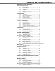
Table of Contents Revisions to This Document Panel Specifications 1.1 1.2 1.3 1.4 1.5 1.6 Power Supply..........................................1 Communication........................................1 Panel Zones.............................................1 Keypads..................................................1 Outputs...................................................1 Enclosure Specifications...........................1 Introduction 2.1 2.2 2.3 2.4 2.5 Description..................................
Table of Contents Annunciator Outputs 12.1 12.2 12.3 Description............................................12 Harness Wiring......................................12 Model 860 Relay Module.........................12 Telephone RJ Connector 13.1 13.2 13.3 13.4 Description............................................13 FCC Registration....................................13 Notification............................................13 Ground Start.........................................13 Reset Jumpers J16 14.
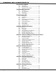
Table of Contents 20.5 20.6 20.7 20.8 20.9 20.10 20.11 20.12 20.13 Mercantile.............................................17 Mercantile Safe and Vault.......................17 Line Security for Police Connect..............17 Standard Line Network Security..............17 Wireless Arming Mode............................17 Wireless Tamper....................................17 Wireless External Contact.......................17 Wireless Supervision Time......................17 Wireless Audible Annunciation....
Revisions Revisions to This Document This section explains the changes that were made to this document during this revision. This section lists the date the change was made, the section number and heading, and a quick summary of the change. Ver. Section Number and Heading Summary of Changes 1.02 3.5 Wiring Diagram Removed reference to Grades of Service 17.4 Network Security Replaced AA High Line with Standard Line 19.6 DACT Central Station Removed reference to Grades of Service 20.
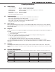
Introduction Panel Specifications 1.1 Power Supply Transformer Input: Wire-in — 16.5 VAC 40 VA, Model 320 Plug-in — 16.5 VAC 40 VA, Model 321 Standby Battery: 12 VDC 7.0 Ah (40 VA transformer charges up to 2 batteries) Auxiliary Output: 12 VDC at 500mA Bell Output: 12 VDC at 1.5 Amps Smoke Detector Output: 12 VDC at 100mA All circuits inherent power limited 1.
Introduction Introduction 2.1 Description The DMP XRSuper6/XR20/XR40 Command Processor™ panels are powerful 12 VDC burglary and fire communicator panels with battery backup. The XR20 and XR40 panels provide nine on-board burglary zones and one on-board 12 VDC Class B powered fire zone. The XRSuper6 provides five burglary zones and one fire zone. The fire zone has a reset capability to provide for 2-wire smoke detectors, relays, or other latching devices.
Introduction System Components 3.1 Description The DMP system is made up of an alarm panel with built in communicator, an enclosure, a 16.5 VAC transformer, and a 12 VDC 7.0 Ah battery. You can add Security Command keypads to the system and can also connect auxiliary devices to the panel’s open collector outputs to expand the basic system. Combined current requirements of additional modules may require an auxiliary power supply.
Introduction 3.4 Accessory Devices continued 1161 Residential Smoke Detector Residential smoke detector with sounder. 1162 Residential Smoke Detector Residential smoke/heat detector with sounder and fixed rate-of-rise heat detector Accessory Modules and Keypads iCOMsl Network Alarm Router Allows network connection for alarm communication * ePAD™ Virtual Keypads Allows users to control the security system from any computer in the world using the Internet.
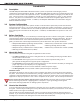
Installation Installation 4.1 Mounting the Enclosure The metal enclosure must be mounted in a secure, dry place to protect the panel from damage due to tampering or the elements. It is not necessary to remove the PCB when installing the enclosure. The PCB may be installed in the standard 340 enclosure the optional 349 Medium enclosure or 341 Kiosk enclosure. The XRSuper6, XR20, or XR40 panels may optionally be installed in the 350A Grade A enclosures.
Installation 4.2 Mounting Keypads DMP keypads have removable covers that allow the base to be mounted on a wall or other flat surface using the screw holes provided on each corner. For mounting keypads on solid walls, or for applications where conduit is required, use a DMP 695, 696, 775, or 776 keypad conduit backbox. 4.
Installation Secondary Power Supply 6.1 Battery Terminals 3 and 4 Connect the black battery lead to the negative battery terminal. The negative terminal connects to the enclosure ground internally through the XRSuper6, XR20, or XR40 circuit board. Connect the red battery lead to the positive battery terminal. Observe polarity when connecting the battery. Add a second battery in parallel using the DMP Model 318 Dual Battery Harness.
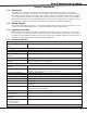
Installation 6.7 XRSuper6/XR20/XR40 Standby Battery Calculations Standby Battery Power Calculations Alarm Current Command Processor Panel Active Zones 1-9 (1-5 on XRSuper6) Active Zone 10 (Zone 6 on XRSuper6) 2-Wire Smoke Detectors Panel Bell Output x x x 1100D Wireless Receiver x 1100DI Wireless Receiver x 50mA 1.6mA 4mA 0.1mA ______mA ______ ______ ______ 50mA *2mA 30mA 0.1mA Max.
Installation Bell Output 7.1 Terminals 5 and 6 Nominal 12 VDC is supplied by terminal 5 on the panel to power alarm bells or horns. The output is rated for a maximum of 1.5 Amps with a 40 VA transformer. This output can be steady, pulsed, or Temporal Code 3 depending upon the Bell Action specified in Output Options programming. Terminal 6 is the ground reference for the bell circuit. Keypad Data Bus 8.1 Description Terminals 7, 8, 9, and 10 of the panel are designated as the keypad data bus.
Installation Burglary Zones 10.1 Description On XR20/XR40 panels, terminals 12 to 24 are the nine burglary zones. For programming purposes, the zone numbers are 1 to 9. The zone configurations on terminals 12 to 24 are described below. The XRSuper6 terminals 12 to 18 are the five burglary zones with terminal 16 providing the ground for zone 5 (terminal 18).
Installation Powered Zone for 2-Wire Smoke Detectors 11.1 Terminals 25 and 26 A resettable 2-wire Class B powered zone is provided on terminals 25 (positive) and 26 (negative) of the panel. For programming purposes, the zone number is 10 on the XR20/XR40 and zone 6 on the XRSuper6. The zone uses a Model 309, 3.3k Ohm EOL resistor (provided with the panel) and has an operating range of 8.8 to 14.2 VDC. The UL compatibility identifier is: A.
Installation Annunciator Outputs 12.1 Description The four annunciator outputs can be programmed to indicate the activity of the panel’s zones or conditions occurring on the system. Annunciator outputs do not provide a voltage but instead switch-to-ground voltage from another source.
Installation Telephone RJ Connector 13.1 Description Connect the panel to the public telephone network by installing a DMP 356 RJ Cable between the panel’s J4 connector and the RJ31X or RJ38X phone jack. A two pin header labeled RJ SUP (J7) is provided to allow monitoring of the telephone cable connected between the panel and a RJ38X jack (pins 2 and 7 jumpered). Attach a DMP Model 306 Harness between J7 and any available zone.
Compliance Reset Jumpers J16 14.1 Description A pair of jumper wires are located at the top right of the panel circuit board labeled RESET. Momentarily shorting these jumper wires allows you to reset the microprocessor. Resetting the panel allows you to enter the panel’s internal programmer. To reset the panel when first installing the system, place the blade of a slotted screwdriver across the two reset jumper wires after applying power to the panel.
Compliance ANSI/UL 1023 Specifications Household Burglar-Alarm System Units 16.1 Bell Cutoff The bell cutoff time cannot be less than five minutes. See the XRSuper6/XR20/XR40 Programming Guide (LT‑0305). 16.2 Entry Delay The maximum entry delay used must not be more than 45 seconds. See the XRSuper6/XR20/XR40 Programming Guide (LT-0305). 16.3 Exit Delay The maximum exit delay used must not be more than 60 seconds. See the Programming Guide (LT-0305). 16.
Compliance 17.8 Wireless Supervision Time The Zone Information Supervision Time cannot be set to 0 (zero). See the XRSuper6, XR20, XR40 Programming Guide (LT-0305). 17.7 Wireless Audible Annunciation The Wireless Audible option must be selected as ANY for commercial applications. ANSI/UL 636 Specifications Holdup Alarm Units 18.
Compliance ANSI/UL 365 Specifications Police Station Connected Systems 20.1 Entry Delay The maximum entry delay must not exceed 60 seconds with the Model 350A housing. See LT-0305. 20.2 Bell A local audible signal appliance must be used. The alarm housing for a mercantile alarm system without a remote alarm transmission connection shall be mounted on the outside of the building, visible from a public street or highway. It shall be accessible for examination and repair.
Compliance ANSI/UL 609 Specifications Local Burglar Alarm Units and Systems 21.1 Entry Delay The maximum entry delay must not exceed 60 seconds with the Model 350A housing. See LT-0305. 21.2 Bell A local audible signal appliance must be used.
Compliance Universal Fire Alarm Specifications 22.1 Introduction The programming and installation specifications contained in this section must be completed when installing the Model XRSuper6/XR20/XR40 in accordance with any of the UL or NFPA fire standards. Additional specifications may be required by a particular standard. 22.2 Wiring All wiring must be in accordance with NEC, ANSI/NFPA 70. 22.
Compliance False Alarm Reduction Programmable Options * 25.1 Shipping Defaults and Recommended Programming for ANSI/SIA CP-01-2000 SIA CP-01 FEATURE PARAGRAPH # AND DESCRIPTION DMP PROGRAMMING GUIDE LT‑0305 SECTION # REQUIREMENT Required 45 sec. - 250 sec.
Compliance False Alarm Reduction Programmable Options (continued) 25.2 Call Waiting (ANSI/SIA CP-01-2000) The Call Waiting default setting is disabled. To cancel the Call Waiting feature, program * (star) 7 0 P (pause), the standard telephone code prefix that cancels call waiting, into the telephone number string. Cancel Call Waiting for telephone lines that have Call Waiting operational on the telephone line. See the XRSuper6/XR20/XR40 Programming Guide (LT‑0305).
Troubleshooting Troubleshooting 26.1 Troubleshooting Section This section of the Installation Guide provides troubleshooting information for use when installing or servicing an XRSuper6/XR20/XR40 system. Problem Possible Cause Possible Solutions J16 Jumper is installed. Remove the J16 reset jumper. Open or short on the green data wire to Keypad displays “SERVICE REQUIRED” the keypad. Keypad display is not functional. When a key is pressed, only a short beep is emitted.
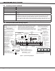
XRSuper6/XR20/XR40 Installation Guide DMP Model 866 37mA at 12 VDC 1k Ω Bell T rouble Bell T rouble Bell B Ð Output Bell B + Output Bell A Ð Output 10 11 9 8 7 6 5 Bell A + Output - 4 Bell Power Ð Input 2 3 1 Bell Power + Input Alarm Input Ground Auxiliary Power Power Supply Trouble Contacts N/C AUXILIARY POWER SUPPLY 8 7 6 5 4 3 2 1 S S S S S S S DMP Model 865 85mA at 12 VDC S S S S S S 12 or 24 VDC 5 Amp Maximum Notification Circuit Module 12 or 24 VDC 5 Am
Wiring Diagrams 27.
OPERATING INSTRUCTIONS MODEL XRSuper6/XR20/XR40 PANELS When using Model 692 LED Keypad, please refer to 692 User Guide (LT-0275) NORMAL STANDBY CONDITION When the system is in the normal standby condition, the keypad shows either the time of day/System Ready or a blank display. ALARM CONDITION When the system is in an alarm condition, the keypad keys glow red and the display shows the violated zone name(s) followed by an alarm display. ARMING THE SYSTEM Press the COMMAND key until arming options appear.