Programming Guide XRSuper6/XR20/XR40 Command Processor™ Panels
MODEL XRSuper6/XR20/XR40 COMMAND PROCESSOR Programming GUIDE When using the Series XRSuper6/XR20/XR40 control for any UL, NFPA, CSFM or other listing organization’s approved methods, refer to this manual and the XRSuper6/XR20/XR40 Installation Guide (LT-0624). These documents outline the installation and programming requirements of all applications for which the XRSuper6/XR20/XR40 is approved.
Table Of Contents Introduction...............................................................1 1.1 1.2 1.3 1.4 1.5 1.6 1.7 1.8 1.9 1.10 1.11 Before You Begin.........................................................1 Programming Information Sheet...................................1 Getting Started............................................................1 Initializing the Panel.....................................................1 Program from any Keypad Address...............................
Table of Contents 3.27 Pager Identification Number.......................................11 Remote Options.......................................................12 4.1 4.2 4.3 4.4 4.5 4.6 4.7 4.8 Remote Options.........................................................12 Remote Key...............................................................12 Manufacturer Authorization........................................12 Armed Rings.............................................................12 Disarmed Rings.....
Table Of Contents 8.4 8.5 8.6 8.7 8.8 8.9 8.10 8.11 8.12 8.13 8.14 8.15 Fire Alarm Output......................................................20 Fire Trouble Output....................................................20 Ambush Output.........................................................20 Entry Output.............................................................21 Exit Output................................................................21 Ready Output....................................................
Table of Contents 11.12.2 11.12.3 11.13 11.14 11.15 11.16 11.17 11.18 Stop 12.1 Output Number.......................................................................32 Output Action..........................................................................33 Swinger Bypass.......................................................................33 Prewarn Address (XR40 only)................................................... 33 Entry Delay.......................................................................
Table Of Contents This page intentionally left blank.
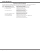
Revisions Revisions to this Document This section explains the changes that made to this document during this revision. This section lists the date the change was made, the section number and section heading, and a quick summary of the change. Version Section Number and Heading Quick Explanation of Changes 1.02 Listings and Approvals Replaced UL AA with Standard Line Security 1.01 6.17 Wireless Audible Annunciation Added Wireless Audible annunciation option. 9.
Introduction Introduction 1.1 Before You Begin Before starting to program, we recommend you read through the contents of this manual. The information in this document allows you to quickly learn the programming options and operational capabilities of the XRSuper6/XR20/XR40 panel. After this Introduction, the remaining sections describe the functions of each programming menu items along with their available options.
Introduction 1.3 Programming Menu You are now ready to start programming the XRSuper6/XR20/XR40 panel. Pressing the COMMAND key scrolls you through the 12 programming menu items listed in below. Note: The 692 Security Command keypad is not suitable for panel programming.
Introduction 1.7 Keypads DMP offers multiple keypads in a variety of styles. All DMP keypads provide the same programming capabilities. Each keypad and its operation are shown and described in the following sections.
Introduction When there are more than four response options available, press the COMMAND key to display the next one to four options. Pressing the Back Arrow key allows you to review the previous four choices. The Select keys/areas are also used for choosing a section from the programming menu. Press any Select key or touch the Select Area when the programming section name you want displays.
Introduction 1.11 Keypad Displays Current Programming Each programming prompt displayed at the keypad shows the currently selected option in the panel memory. These options are either shown as a number, a blank, or a NO or YES. To change a number or blank to a new number, press any top row Select key or touch any Select Area. The current option is replaced with a dash. Press the number(s) on the keypad you want to enter as the new number for that prompt.
Initialization Initialization 2.1 Initialization Initialization This function allows you to set the panel’s programmed memory back to the factory defaults in preparation for system programming. After you select YES to clear a section of memory, the panel asks if you are sure you want to clear the memory. This is a safeguard against accidently erasing part of your programming. No memory is cleared from the programming until you answer YES to the SURE? YES NO prompt.
Communication Communication 3.1 COMMUNICATION 3.2 Comm Type: NONE Communication The Communication section allows you to configure the communication settings for the XRSuper6/XR20/XR40 panel. After choosing the Communication Type, continue through the list of options. Communication Type This specifies the communication method the panel uses to contact the receiver. Press any Select key/area to display the following communication options: None DD 4-2 M2E NONE - For local systems.
Communication 3.3 Account Number Accnt NO: 12345 Enter the account number sent to the receiver. DD, NET - The range of account numbers for Digital Dialer and Network is 1 to 65535. For account numbers of four digits or less, you do not have to enter leading zeros. The panel automatically right justifies the account number. 4-2, M2E, and CID - The account number range for these formats is 1 - 9999. 3.
Communication 3.9 Test Time 00:00 AM Test Time PM Press COMMAND to enter the Test Time. Enter the time of day the panel sends the test report to the SCS-1R Receiver. Use entries between 12:00 to 11:59 and then choose AM or PM. Automatic test messages are sent through the dialer unless NET is programmed as Main Communication and no telephone numbers have been programmed. Then the test message is sent through the network. 3.
Communication 3.18 Receiver 2 Prog Receiver 2 Programming Repeat the instructions for Receiver 1 programming when communicating to a second receiver. Receiver 2 defaults are set to NO. If you select YES for any of the Receiver 2 options, you must have at least one phone number programmed in Receiver 2 programming. 3.
Communication 3.26 Second Phone NO. - Second Telephone Number The panel dials the second number when two successive attempts failed using the first number. If the panel cannot reach the receiver after two attempts using the second number, it returns to the first number and makes two additional attempts. A total of ten dialing attempts are made using the first and second phone numbers. If a second phone number is not entered, the first phone number is used for all dialing attempts.
Remote Options Remote Options 4.1 Remote Options Remote Options This section allows you to enter the information needed for Remote Command/ Remote Programming operation. A description of the Remote Options follows: 4.2 Remote Key RMT Key: This option allows you to enter a code of up to eight digits for use in verifying the authority of an alarm or service receiver to perform a remote command/ programming session. The receiver must give the correct key to the panel before being allowed access.
Remote Options 4.7 Serv Rec NO Yes Service Receiver Authorization YES enables remote commands and programming to be accepted from a secondary service receiver other than the alarm SCS-1R Receiver. The Remote Key option can also be required. With YES selected, the panel requests the service receiver key the first time it is contacted by the service receiver. The panel retains this service receiver key in memory and accepts remote commands from the service receiver.
System Reports System Reports 5.1 System Reports System Reports This function allows you to select the reports the XRSuper6/XR20/XR40 send to the receiver. 5.2 Opn/Clos NO Opening/Closing Reports No YES LTD ALM This option allows the selection of Opening/Closing Reports and the number of reports sent to the receiver. NO - Opening/Closing Reports are not sent by the panel. YES - The panel will send Opening/Closing Reports for each programmed area.
System Options System Options 6.1 System Options System Options This section allows you to select system wide parameters used in the operation of the XRSuper6/XR20/XR40 system. A description of each System Option follows: 6.2 MODE: ALL/PERIM Mode This configures the panel as either a four Area system (XR20/XR40 only), an All/ AREA A/P H/A Perimeter system (Perimeter/Interior), or a Home/Away system (Perimeter, Interior, and Bedrooms). Zones must be assigned to Bedrooms for the area to be active.
System Options 6.6 Exit Delay: 60 Exit Delay Enter the Exit Delay time for all Exit type zones. When the exit delay time starts, all activity on exit and burglary zones is ignored until the exit delay expires. The keypad displays the Exit Delay time countdown and annunciates the Exit Delay tone at 8 second intervals until the last 10 seconds when annunciation is at 3 second intervals. The exit delay can be from 45 to 250 seconds. Default is 60 seconds.
System Options 6.11 Zone Activity Hours Zn Acty Hours: This option allows you to monitor a person living alone for non-activity. Enter the number of hours, 0 to 9, allowed to elapse without a disarmed zone being tripped before a message is sent to the receiver. Default is 0 (zero). When the system is disarmed, the timer begins to countdown the number of hours programmed. Each time activity occurs, the timer restarts the countdown.
System Options 6.15 6.16 HOUSE CODE: 0 DET JAMNG no yes House Code When using a DMP wireless system, enter a house code between 1 and 50 for the wireless system to use. The DMP wireless receiver automatically programs the house code into the wireless transmitters when the unique transmitter serial number is programmed into the panel. See Wireless programming in Zone Information. Default is 0 (zero) indicating the DMP wireless system is not being used.
Output Options Bell Options 7.1 Bell Options BELL Options This section allows you to program the panel bell output functions. 7.2 Bell Cutoff: 5 Bell Cutoff Time Enter the maximum time from 1 to 15 minutes the Bell Output remains on. If the Bell Output is manually silenced or the system is disarmed, the cutoff time is reset. Enter zero to provide continuous bell output. Default is 5.
Output Options Output Options 8.1 Output Options OUTPUT Options This section allows you to program panel output options. Switched Ground (open collector) outputs are available using the 4-wire output harness on the XRSuper6/ XR20/XR40 board. Wireless outputs are available when using the 1100D Wireless Receiver and 1100 Series wireless outputs. Refer to the XRSuper6/XR20/XR40 Installation Guide (LT-0624) for complete information.
Output Options 8.7 Entry Out: 0 Entry Output This output turns on at the start of the entry delay time. The output turns off when the area disarms or the entry delay time expires. Enter 0 (zero) to disable. 8.8 Exit Out: 0 Exit Output This output turns on any time an exit delay time starts. The output turns off when the system arms or when the arming has been stopped. Enter 0 (zero) to disable. 8.
Output Options 8.14 Late Cls Out: 0 Late To Close Output (XR20/XR40 Only) Enter the output number to turn on at the expiration of a closing schedule when all areas are not armed. The output activates simultaneously with the CLOSING TIME! keypad display. The output is turned off when all areas are armed, the closing is extended, or the schedule is changed. 8.15 ARm-Alarm Out: 0 Arm-Alarm Output Enter the output number to turn on steady when any area of the system is armed.
Output Information Output Information 9.1 OUTPUT info Output Information This section allows you to program and name wireless outputs into the panel when using an 1100D Wireless Receiver. Output Information only displays when a House Code (1-50) is entered in System Options programming. 9.2 Output No: XX Output Number Enter an output number. Entry range is 31 to 34, 41 to 44.
Area Information Area Information 10.1 Area Information Area Information (XR20/XR40 Only) This section allows you to assign functions to individual areas for XR20 and XR40 panels. All non-24-hour zones must be assigned to an active area. See the section on Zone Information. Note: Area Information programming is only available on XR20 and XR40 panels. Activate an area by assigning it a name. A name is given to each active area in place of a number to assist the user during arming and disarming. 10.
Zone Information Zone Information 11.1 Zone Information Zone Information This allows you to define the operation of each protection zone used in the system. 11.2 Zone Number Zone No: - Enter the number of the zone you intend to program. Press COMMAND to enter a zone name. Refer to the Enter Alpha Characters section.
Zone Information -- nt dy ex Blank, Night, Day, or Exit. Press COMMAND to display additional zone types. Fi pn em sv Fire, Panic, Emergency, or Supervisory. Press COMMAND to display additional zone types. A1 a2 fv AR Auxiliary 1, Auxiliary 2, Fire Verify, or Arming. Press the Back Arrow key to display the previous zone types. If you select Blank, Night, Day, Exit, Auxiliary 1, or Auxiliary 2 as the Zone Type, the zone must be assigned to an area.
Zone Information 11.7.1 Style: Toggle Style This option specifies the style for the arming/disarming operation. The default for STYLE: is TGL (toggle). Pressing any Select key displays the STYLE options. To view more style options press the command key. The following is a description of the action for each option condition. Tgl Arm DIs Step TGL (Toggle) - When the zone changes from normal to shorted, the programmed areas toggle between the armed or disarmed condition.
Zone Information 11.9 WIRELESS NO YES 11.9.1 SERIAL #: - Wireless Select YES to program this zone as a DMP wireless zone. You must program the wireless House Code prior to adding wireless zones to the system. See House code programming in System Options. Default is NO. Serial Number Entry Enter the eight digit serial number, including leading zeros, found on the wireless device. Already USED zxx Displays when the serial number is already programmed for another zone.
Zone Information 11.9.3 SUPRVSN TIME: xx Supervision Time Press any top row key to select the supervision time required for the wireless zone. Press COMMAND to accept the default time. Default is 240 minutes. 0 3 60 240 Select the required number of minutes. The transmitter must check in at least once during this time or a missing condition is indicated for that zone.
Zone Information 11.10.3 SUPRVSN TIME: 0 Key Fob Supervision Time Press any top row key to select the supervision time required for the key fob zone. Press COMMAND to accept the default time. Default is 0. 0 3 60 240 Press the Select key under the required number of minutes. The key fob must check in at least once during this time or a missing condition is indicated for that zone.
Zone Information 11.10.8 Press Time: xxxxx Button Press Time This option specifies the amount of time (SHORT or LONG) the user must press the button before the key fob sends a message to the wireless receiver. The default press time displays. Press any Select key to set the Button Press Time for Arm, Disarm, Toggle, Status, Output, and Sensor Reset. Note: The Button Press Time is not programmable on Panic (PN or PN2), Emergency (EM or EM2) or Unused (UN) zones.
Zone Information 11.11 Alarm Action Alarm Action . . . The Alarm Action section allows you to change or confirm the default alarm characteristics of a zone type. If you selected the non-24-hour zone type Blank, Night, Day, Exit, Auxiliary 1, or Auxiliary 2, the Alarm Action programing begins with Disarmed Open. If you selected the 24-hour zone type Fire, Panic, Emergency, or Supervisory, the Alarm Action programming begins with Armed Open.
Zone Information 11.12.3 Action: Output Action Entering an Output Number displays this prompt that allows you to assign an output action to the relay. A description of the available output actions is given below: STD Pls Mom FOLW STEADY - The output is turned on and remains on until the area is disarmed, an output cutoff time expires, or the output is reset from the keypad User Menu.
Zone Information 11.16 Crs Zone NO YES Cross Zone Select YES to enable cross-zoning for this zone. Cross-zoning requires this zone to trip twice, or this zone and another cross-zoned zone to trip, within a programmed time before an alarm report is sent to the receiver. Note: To operate correctly, all cross-zone zones need to be programmed as the same zone type. When a cross-zoned zone trips, the Output action assigned to the zone activates. See the Bell Action section.
Stop Stop 12.1 Stop Stop At the STOP prompt, pressing any Select key allows you to exit the programmer function of the XRSuper6/XR20/XR40 panel. When selected, the panel performs an internal reset and exits the programmer. The Stop function causes the following conditions to occur: • • • The system is DISARMED All 1100 Series DMP Wireless transmitters are reset to NORMAL The panel’s Status List is CLEARED During the Stop function, all keypad displays are momentarily blank for two seconds.
Appendix Appendix This section of the XRSuper6/XR20/XR40 Programming Guide provides additional zone and system information. 14.1 Status List The Status List is the current status of the system or records of recent system events that display on alphanumeric keypads. For example, in Home/Away systems you may see the display SYSTEM READY. If an event were to occur on the system, such as an AC failure, the keypad would also display the AC POWER -TRBL message.
Appendix 14.4 Manual Telephone Line Seizure for Remote Programming This feature allows you to connect to a service receiver, primarily used to bring a new account on-line as it allows you to upload panel programming completed in Remote Link™. There are two options to allow manual phone line seizure: Number and Pickup. Using the Number method, the phone number of the service receiver connected to Remote Link is entered. The panel will then call the receiver.
Appendix 14.5 Using the Walk Test The XRSuper6, XR20, and XR40 panels provides a walk test feature that allows a single technician to test all the protection devices connected to zones on the system. Conduct the Walk Test within 30 minutes of resetting the panel. The Walk Test automatically ends if no zones are tripped for 20 minutes. TEST IN PROGRESS displays at all keypads. When five minutes remain, TEST END WARNING displays. If any areas are armed the Walk Test does not start and SYSTEM ARMED displays.
Appendix 14.6 Keypad Speaker Operation When using LCD Keypads, the panel provides distinct speaker tones from the keypad for Fire, Burglary, Zone Monitor, and Prewarn events. The list below details the conditions under which the speaker is turned on and off for each event. Fire On - Fire zone alarm and Bell Output are ON. Off - Alarm Silence or briefly when a key is pressed. Burglary On - Burglary zone alarm and Bell Output and is ON. Off - Alarm Silence or briefly when a key is pressed.
Appendix The third column from the left is the second digit of the 2-digit event code sent to the receiver. The fourth column (on the right) is what that character represents.
Appendix 14.9 FA426 Wireless Operation The FA426 is a 900MHz wireless receiver that installs in the enclosure of the XRSuper6/XR20/XR40 Command Processor and allows you to add up to 16 wireless expansion zones to the panel. A wire harness included with the FA426 plugs into the receiver and connects to the keypad bus terminals on the panel.
Appendix 14.10 Zone Type Descriptions This section describes applications for the default zone types in Zone Information programming. NT (Night Zone) - Controlled instant zone used for perimeter doors and windows and interior devices such as PIRs and glassbreak detectors. DY (Day zone) - Used for emergency doors or fire doors to sound the keypad buzzer and display the zone name when the zone is faulted. Day zones also will send alarm reports to the receiver during the system’s armed periods.
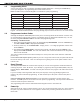
N Priority TGL 1 or 2 1-2 Prewarn (XR40 only) to 8 1-8 S S S S S S S S S S S S 0 0 0 0 A A A A 0 0 T T S S S 0 0 0 – T – Y Y Y Y Y Y Y Y Y Y Y 240 240 240 240 240 240 240 240 240 240 240 = This function not available for this zone type. Outputs = 1 to 4, 31 to 34, or 41 to 44.
14.12 Common Keypad Messages Message Meaning Possible Solutions INVALID CODE The user code you have entered is not recognized by the system. Check the user code and try again. CLOSING TIME (XR20/XR40 Only) The schedule has expired but the system has not been armed. Users still on the premise should arm the system or extend the schedule to a later time. AC TROUBLE The system is not getting proper power. Check that the AC connections are good.