
Installation Guide


2 1100T INSTALLATION GUIDE | DIGITAL MONITORING PRODUCTS
3
The 1100T translator provides a Survey LED capability to allow one person to confirm communication with the
panel while the cover is removed.
1. With the cover removed, hold the translator in the exact desired location.
2. Press the tamper switch to send data to the panel and determine if communication is confirmed or
faulty.
Confirmed: If communication is confirmed, for each press or release of the tamper switch, the LED
blinks immediately on and immediately o. Repeat this test 5 times to confirm ten separate
consecutive LED blinks. Any indication otherwise means proper communication has not been
established.
Faulty: If communication is faulty, the LED remains on for about 8 seconds or flashes multiple times
in quick succession. Relocate the translator or receiver until the LED confirms clear communication.
SELECT A LOCATION
MOUNT THE TRANSLATOR
The translator must be mounted using the provided #6
screws in the four mounting holes. Mount the translator
in a secure, dry place away from metal objects to
protect the panel from damage due to tampering or the
elements. Mount the translator a minimum of 4 feet from
any wireless panels or repeaters. It is not necessary to
remove the PCB when installing the enclosure.
4
POWER THE TRANSLATOR
2
Wire the Power Supply
The 1100T can be powered from a 12 VDC external
power supply. In addition to powering the 1100T, the
power supply also charges the back-up battery. If
the DC power source is removed, the power failure is
indicated as an open condition on the 1100T zone.
The 372-500-W must be located within 100 feet of
the panel using 22 AWG wire. Use the following steps
to connect the model 372-500-W plug-in DC power
supply to the 1100T:
1. Connect the positive wire to the positive
terminal on the 1100T.
2. Connect the negative wire to the negative terminal on the 1100T.
3. Plug the power supply into a wall outlet not controlled by a switch.
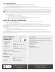
Mounting Hole Locations
+B AT- +12V-
-
+