
User's Manual

2 1158 INSTALLATION GUIDE | DIGITAL MONITORING PRODUCTS
To power the 1158, transfer AC power from the existing panel to the 1158. If a backup battery
is attached to the existing panel, it can also be transfered. Use 18-22 gauge wire for all wiring
connections.
1. Connect the 1158's AC power terminals to the existing panel's 16.5VAC power supply. See
Figure 3.
2. Connect the 1158's negative and positive DC OUTPUT terminals to any zones that require
separate power, if necessary.
3. Ensuring that polarity is correct, connect the 1158's negative and positive BAT terminals to
the existing panel's backup battery, if necessary.
4. Snap the 1158 housing cover into place.
Wire the contacts and connect the receiver before connecting power to the 1158.
1. Locate the existing normally closed contacts you would like to connect to the 1158. These
contacts should be within 2,500 feet of the 1158.
2. Use 18–22 gauge wire to connect a contact to a zone terminal and a ground (GND) terminal.
See Figure 2.
3. Repeat Step 2 for the remaining contacts, as needed.
Note: When wiring new contacts, EOL resistors do not need to be used. However, if exsiting
contacts have EOL resistors installed, they do not need to be changed or removed.
3
WIRE THE 1158 CONTACTS
4
POWER THE 1158
2
MOUNT THE 1158
The 1158 should be placed close to the existing non-DMP panel.
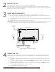
With the 1158's housing cover removed, use the supplied screws to secure the 1158 to a wall or
other flat surface. The 1158 PCB has built-in holes to allow you to screw the housing onto a surface
without removing the PCB. See Figure 2.
Figure 2: 1158 Zone and Power Wiring
To Zone 1
To Powered
Zones
To 16.5VAC
Power
To Backup
Battery
Mounting
Hole
Mounting
Hole
Mounting
Hole