Product End-of-Life Disassembly Instr uctions Product Category: Monitors and Displays Marketing Name / Model [List multiple models if applicable.] HP L2105tm Touchscreen Monitor Name / Model #2 Name / Model #3 Name / Model #4 Name / Model #5 Purpose: The document is intended for use by end-of-life recyclers or treatment facilities.
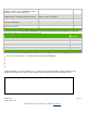
Plastics containing Brominated Flame Retardants weighing > 25 grams (not including PCBs or PCAs already listed as a separate item above) HB No Components and parts containing toner and ink, including liquids, semi-liquids (gel/paste) and toner Include the cartridges, print heads, tubes, vent chambers, and service stations.
USER’S MANUAL HP Compaq L2105tm HSTND-2791-Q
First Edition (October 2009) Document Part Number: 582769-001 Copyright © 2008 HP. All Rights Reserved. No part of this manual, including the products and software described in it, may be reproduced, transmitted, transcribed, stored in a retrieval system, or translated into any language in any form or by any means, except documentation kept by the purchaser for backup purposes, without the express written permission of HP.
Agency Regulatory Notices Federal Communications Commission Notice This equipment has been tested and found to comply with the limits for a Class B digital device, pursuant to Part 15 of the FCC Rules. These limits are designed to provide reasonable protection against harmful interference in a residential installation.
Canadian Notice This Class B digital apparatus meets all requirements of the Canadian Interference-Causing EquipmentRegulations. Avis Canadien Cet appareil numérique de la classe B respecte toutes les exigences du Règlement sur le matérielbrouilleur du Canada. Japanese Notice Korean Notice Power Cord Set Requirements The monitor power supply is provided with Automatic Line Switching (ALS). This feature allows the monitor to operate on input voltages between 100–120V or 200–240V.
Product Environmental Notices Materials Disposal This HP product contains mercury in the fluorescent lamp in the display LCD that might require special handling at end-of-life. Disposal of this material can be regulated because of environmental considerations. For disposal or recycling information, contact the local authorities or the Electronic Industries Alliance (EIA)http://www.eiae.org.
Table of Contents Safety Instructions ............................................................................................................... 2 Recycling Information .......................................................................................................... 3 System components and accessories ................................................................................ 4 Connection instructions ........................................................................................
Safety Instructions • Please keep the display away from any heat sources such as electric radiators or direct sunlight. Place the display in a stable and well-ventilated place. • The holes or openings on the display are designed for ventilation. Do not cover or block the ventilation holes or openings with any objects. • As the display surface is vulnerable to scratches, avoid touching the surface with nail or pen point. • Shut off the power supply before cleaning.
Recycling Information HP encourages customers to recycle used electronic hardware, HP original print cartridges, and rechargeable batteries. For more information about recycling programs, go to http://www.hp.com/recycle.
System components and accessories LCD display Signal cable (VGA) Quick Start Guide Power cord USB cable Audio cable DVI cable User's manual (CD) Quick Start Guide If any component is missing, please contact your local dealer for technical support or customer service. Note: Please keep the original carton and packing materials for future transportation or shipment of the display.
Connection instructions Installing the display Install: Remove: Place the display on the table (Figure 1) Packaging procedures If you need to package the display again, please keep the original carton and packing materials. The procedures for re-packaging the display are as follows: 1. Unplug the power cord from the display (make sure all attached peripherals are already turned off). 2. Put the display into the carton in the original packaging manner.
Connection instructions Note: Before installation, please make sure to power off the display and the computer. (Figure 3) 1 Power cord ○ 2 VGA cable ○ 3 Audio cable ○ 4 USB cable ○ Connect one end of the power cord into the AC power connector on the rear of the display, and the other end to an electrical wall outlet. Connect the signal cable: - For analog operation use the VGA cable. Connect the VGA signal cable to the VGA connector on the rear of the PC. - For digital operation use the DVI-D cable.
Using the display Turning on the display Turn on the display before turning on the computer. When the power is on, the LED on the power button lights blue and the screen image will appear after about 10 seconds. If the LED doesn't light blue or no image appears, please verify if the display is properly connected.
Driver Installation Guide for Windows XP 1.Installation Step1: Click OTM_Driver_Setup.exe To install OTM driver need OTM devices. If the setup wizard can’t found the OTM devices, it would pop up following warning message.
Step3: click “Install” After clicking install, the setup wizard would pop the window which shows the installation process, Step4: Click “Continue anyway” or “Install driver software anyway” When setup wizard is installing OTM driver on XP, the windows system would pop up a warning window.
Step5: Click “Finish” Installation Complete Step6: Click Yes After Clicking Finish, the setup wizard would ask the user to reboot computer for runing OTM_Apps applications. 2.Silent install Step 1. Copy OTM_Driver_Setup.exe to a directory Step 2. Execute command prompt Step 3. Change path to the directory Step 4. Type “OTM_Driver_Setup.exe /S” P.S. Silent Install need reboot computer manually.
Control of the Touch Function Note: 1. Before using the touch function, make sure that USB is connected, the applications attached to the driver CD-ROM are installed and the Window's operating system is started. 2. When the touch function is active, make sure there is no foreign object in the areas encircled in the figure below. (Figure 5) Make sure there is no foreign object in the encircled areas.
OSD selection Press the Menu button to activate the OSD function menu and continue pressing the Menu button to select an option from the 7 functions in the menu. Select the function you want to adjust on the OSD function menu and then press MENU to make adjustment. Please use to adjust the screen to your desired status. After finishing the setting, press AUTO to exit the OSD screen. OSD Menu Brightness/Contrast 2 and ○ 3 in Figure 4) to adjust the Brightness: Press < or > (○ brightness.
OSD CONTROL H.OSD POSITION: Controls the OSD menu’s horizontal position. V.OSD POSITION: Controls the OSD menu’s vertical position. OSD TIMEOUT: Determines how long (in seconds) the OSD menu waits before closing automatically after no action has been performed. OTHER LANGUAGE: OSD menu language selection: ENGLISH,DEUTSCH,FRANCAIS,ESPANOL,ITALIANO,POLSKI, NEDERLANDS,PYCCKO. INPUT: Selects Analog (D-sub) or Digital (DVI-D) input. SPEAKER VOLUME: Adjusts the monitor loudspeaker output volume.
Troubleshooting Problems Possible solutions Power LED doesn't light up. • Check if the power switch is in the ON position • Make sure the power cord is properly connected No screen image • • • • Abnormal colors are present • Please refer to the "Color Temperature" section to adjust the RGB color or select a color temperature. The image bounces or a wave pattern is present • Remove any electrical device that may be causing electrical interference.
Production Specifications LCD panel size 54.61 cm(21.5in) DCR 3000:1 (typical) Viewing angle Horizontal 170°, vertical 160° (typical) Response time 5 ms (typical) Brightness 300 cd/m2 (typical) Input signal Analog signal (D-sub); digital signal (DVI) Display color 16.7 M colors Frequency 24 ~ 83 kHz Horizontal, 50 ~ 76 Hz Vertical Max resolution 1920 x 1080(60Hz) Max Pixel clock 180 MHZ Tilt -5° ~ 20° Audio output 1W X 2 Power supply 100-240VAC, 50/60Hz, 1.
Preset Modes Preset Pixel Horz Freq (kHz) Horz Polarity Vert Freq (Hz) Vert Polarity Pixel Clk (MHz) Source 1 640 x 480 31.469 - 59.940 - 25.175 VGA 2 720 x 400 31.469 - 70.087 + 28.322 VGA 3 800 x 600 37.879 + 60.317 + 40.000 VESA 4 1024 x 768 48.363 - 60.004 - 65.000 VESA 5 1280 x 720 45.00 + 60.00 + 74.25 VESA/CEA-861D 6 1280 x 960 60.00 ± 60.00 ± 108.000 VESA 7 1280 x 1024 63.98 + 60.02 + 108.000 VESA 8 1440 x 900 55.94 - 59.89 + 106.
Appendix Connector pin assignment • 15 pin color display signal cable: PIN No. Description PIN No. Description 1. Red 9. +5V 2. Green 10. Logic ground 3. Blue 11. Monitor ground 4. Monitor ground 12. DDC-serial data 5. DDC-return 13. H-sync 6. R-ground 14. V-sync 7. G-ground 15. DDC-serial time sequence 8.