
Installation guide

Digital Monitoring Products 7760 Keypad Installation Guide
2
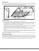
Harness Wiring
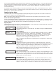
Figure 3 shows wiring harness mounting location and wiring assignments. Observe wire colors when connecting the
Red, Yellow, Green, and Black wires to the keypad bus. When wiring directly to the panel terminals, connect Red to
panel terminal 7, Yellow to terminal 8, Green to 9, and Black to panel terminal 10.
Black – Ground
Green – Receive Data
Yellow – Send Data
Red – Keypad Power
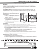
Surface Mounting
Screws (2)
Squeeze latches to
connect keypad cover to back.
Leg
Glass
Keypad
Front
Building
Wall
Plug 4-Wire Harness
into J4 Header
To
Panel
Keypad
Bus
Cover Hinge (4)
AC/Armed LED
Glass
Keypad Rear
Legs (2)
Figure 3: Keypad Side Mounting and Back Showing Wiring Harness Assignments
Wiring Specications
When planning a keypad bus installation, keep in mind the following specications:
1. DMP recommends using 18 or 22‑gauge unshielded wire for all keypad and LX‑Bus circuits. Do Not use twisted
pair or shielded wire for LX‑Bus and keypad bus data circuits. To maintain auxiliary power integrity when
using 22‑gauge wire do not exceed 500 feet. When using 18‑gauge wire do not exceed 1,000 feet. Install an
additional power supply to increase the wire length or add devices.
2. Maximum distance for any one circuit (length of wire) is 2,500 feet regardless of the wire gauge. This distance
can be in the form of one long wire run or multiple branches with all wiring totaling no more than 2,500 feet.
As wire distance from the panel increases, DC voltage on the wire decreases.
3. Each panel allows a specic number of supervised keypads. Additional keypads can be added in the
unsupervised mode. Refer to the panel installation guide for the specic number of supervised keypads
allowed.
4. Maximum voltage drop between the panel (or auxiliary power supply) and any device is 2.0 VDC. If the voltage
at any device is less than the required level, add an auxiliary power supply at the end of the circuit. When
voltage is too low, the devices cannot operate properly.
Refer to the LX‑Bus/Keypad Bus Wiring Application Note (LT‑2031). Also see the 710/710F Module Installation Sheet
(LT‑0310) for more information.
Additional Power Supply
If the current draw for all keypads exceeds the panel output, you can provide additional current by adding a Model
505‑12 auxiliary power supply. Connect all keypad Black ground wires to the power supply negative terminal. Run
a wire from the power supply negative terminal to the panel common ground terminal 10. Connect all keypad Red
power wires to the power supply positive terminal. Do NOT connect the power supply positive terminal to any panel
terminal. Refer to the 504‑24 and 505‑12 Power Supply Installation Guide (LT‑0453) for more information.