
Installation guide


Table Of Contents
- Keypad Installation Guide
- DMP Keypads
- Installing the Keypad
- Harness Wiring
- Additional Power Supply
- Keypad Bus Monitor
- Card Readers
- Door Strike Relay Specifications (7073/7073A, 793 only)
- Zone 2 Door Contact with Soft-Shunt™ (7073/7073A, 793 only)
- Zone 3 Request to Exit (7073/7073A, 793 only)
- Panic Key Options
- Internal Speaker Operation
- Backlighting
- End-User Options
- Entering Alpha Characters
- Entering Non-Alphanumeric Characters
- Installer Options Menu
- Additional Programming 7063/7063A, 7073/7073A, and 693/793 Keypads
- User’s Guide
- Keypad Arming and Disarming
- Keypad Door Strike
- Keypad Entry Delay
- FCC Information
- Wiring Specifications
- Keypad Specifications
- Specifications
- Compatibility
- Listings and Approvals
- Accessories
2 LCD Keypad Installation Guide
LCD Keypad Installation Guide 3
Surface and Backbox
Mounting Holes
Combined 4-square
and 3-gang switch box
Mounting Holes
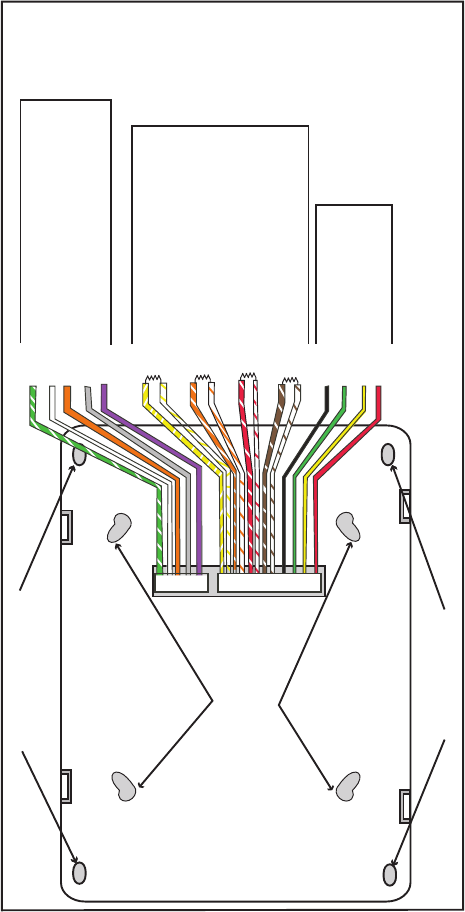
Keypad Back
Surface and Backbox
Mounting Holes
1K EOL
1K EOL
1K EOL
1K EOL
Green/White – Connect Reader Data 0
White – Connect Reader Data 1
Orange – Door Strike Normally Open
Gray – Door Strike Common
Violet
– Door Strike Normally Closed
Yellow/White
White/Yello
w
Orange White
White/Orange
Red/White
White/Re
d
Brown/White
White/Brow
n
Black – Ground
Green – Receive Data
Yellow – Send Data
Red – Keypad Power
– Zone
4
– Zone
3
– Zone 2
– Zone 1
External
Reader
/
Door Strike
7073/7073A,
793 Keypads
Zones
1 through
4
7070/7070A
,
7073/7073A,
790/790F, and
793 Keypads
All Keypads
Figure 1: Keypad Back Showing Wiring Harness Assignments