
Specifications


smartModule Express SMX945 / BIOS
www.kontron.com 65
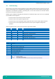
CMOS Map
Location Description
12h Fixed (Hard) Drives
Bits 7-4 = Hard Drive 0, AT Type
0000 = Not installed
0001-1110 = Types 1-14
1111 = Extended drive types 16-44.
See location 19h.
Bits 3-0 = Hard Drive 1, AT Type
0000 = Not installed
0001-1110 = Types 1-14
1111 = Extended drive types 16-44.
See location 2Ah.
13h Reserved
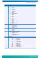
14h Equipment
Bits 7-6 = Number of Diskette Drives
00 = One diskette drive
01 = Two diskette drives
10, 11 = Reserved
Bits 5-4 = Primary Display Type
00 = Adapter with option ROM
01 = CGA in 40 column mode
10 = CGA in 80 column mode
11 = Monochrome
Bits 3-2 = Reserved
Bit 1 = Math Coprocessor Presence
0 Not installed
1 Installed
Bit 0 = Bootable Diskette Drive
0 Not installed
1 Installed
15h Base Memory Size (in kB) - Low Byte
16h Base Memory Size (in kB) - High Byte
17h Extended Memory Size (in kB) - Low Byte
18h Extended Memory Size (in kB) - High Byte
19h Extended Drive Type - Hard Drive 0
1Ah Extended Drive Type - Hard Drive 1
1Bh Custom and Fixed (Hard) Drive Flags
Bits 7-6 = Reserved
Bit 5 = Internal Floppy Disk Controller
0 Disabled
1 Enabled
Bit 4 = Internal IDE Controller
0 Disabled
1 Enabled
Bit 3 = Hard Drive 0 Custom Flag
0 Disabled
1 Enabled
Bit 2 = Hard Drive 0 IDE Flag
0 Disabled
1 Enabled
Bit 1 = Hard Drive 1 Custom Flag
0 Disabled
1 Enabled
Bit 0 = Hard Drive 1 IDE Flag
0 Disabled
1 Enabled
1Ch Reserved
1Dh EMS Memory Size Low Byte
1Eh EMS Memory Size High Byte
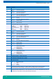
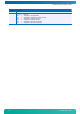
1Fh - 24h Custom Drive Table 0
These 6 Bytes (48 bits) contain the following data:
Cylinders 10bits range 0-1023
Landing Zone 10bits range 0-1023
Write Precompensation 10bits range 0-1023
Heads 8bits range 0-15
Sectors/Track 8bits range 0-254