
User manual


Kontron Compact Computers AG SMX945 Detailed Manual V1.1
60
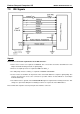
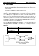
7.5. LAN Signals
Component placement can affect signal quality, emissions, and temperature of a board design.
Decrease potential problems directly related to electromagnetic interference (EMI), which could cause
failure to meet FCC.
Simplify the task of routing traces. To some extent, component orientation will affect complexity of
trace routing. The overall objective is to minimize turns and crossovers.
Minimizing the amount of space needed for the Ethernet LAN interface is important because all other
interfaces will compete for physical space on a motherboard near the connector edge. As with most
subsystems, the Ethernet LAN circuits need to be as close as possible to the connector. To minimize the
effects of EMI, clock sources should not be placed near I/O ports or board edges. Radiation from these
devices may be coupled onto the I/O ports or out of the system chassis.
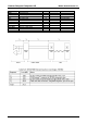
Crystals should also be kept away from the Ethernet magnetics module to prevent interference of
communication. The retaining straps of the crystal, if they exist, should be grounded to prevent possible
radiation from the crystal case. The crystal should lay flat against the PC board to provide better coupling of
the electromagnetic fields to the board. For a noise free and stable operation, place the crystal and
associated discrete components as close as possible to the Intel 82562ET/EM, keeping the trace length as
short as possible and do not route any noise signals in this area.
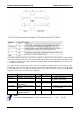
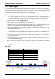
The 100 Ohms ± 1% resistor used to terminate the differential transmit pairs (TDP/TDN) and the 121 Ohms
± 1% receive differential pairs (RDP/RDN) and should be placed as close to the platform LAN connect
component (Intel 82562ET or Intel 82562EM) as possible. This is due to the fact that these resistors are
terminating the entire impedance that is seen at the termination source (i.e. Intel 82562ET).
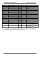
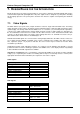
LAN Signals:
Signal Group LAN
Topology Differential
Referred plane Ground
Impedance 55 Ohm +/-1%
Trace with / pair spacing 4mil / 7mil
Number of allowed vias 2
Maximal length 20cm
Length matching +/- 1mm
Remarks: -