
User manual


Kontron Compact Computers AG SMX945 Detailed Manual V1.1
57
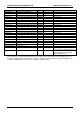
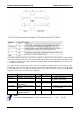
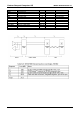
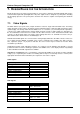
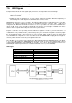
7.2. IDE Signals
Signals:
Follow these connection requirements for an IDE connector:
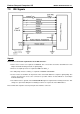
22-47 series resistors are required on RESET#. The correct value should be determined for each
unique motherboard design, based on signal quality.
An 8.2 to 10 k pull-up resistor is required on IRQ14 to VCC3_3.
A 4.7kΩ pull-up resistor to VCC3_3 is required on PIORDY and SIORDY.
Series resistors of 10 Ohms can be placed on the control and data lines to improve signal quality. The
resistors are placed as close to the connector as possible. Values are determined for each unique
motherboard design.
The 10kΩ resistor to ground on the PDIAG#/CBLID# signal is required on the Primary Connector. This
change is to prevent the GPI pin from floating if a device is not present on the IDE interface.
Place a 22uF/10V capacitor at each power pin of the interface connector.