
User manual


Kontron Compact Computers AG SMX945 Detailed Manual V1.1
55
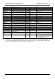
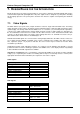
Signal Description I/O Termination Remarks
RSMRST# Resume / reset input I 3.3VSB PU 100k 3.3VSB
SMBALRT#
System management bus alert in I 3.3VSB PU 100k 3.3VSB
BATLOW# Battery low input I 3.3VSB PU 100k 3.3VSB
GPE1# General purpose power
management event input 1
I 3.3VSB PU 100k 3.3VSB
GPE2# General purpose power
management event input 2
I 3.3VSB PU 100k 3.3VSB
EXTSMI# System management interrupt input I 3.3VSB PU 100k 3.3VSB
PWGIN Power good input I Also usable as a reset input;
make low with
O.C. to cause reset
5V_ALW Supply of internal suspend circuit Power-In Input voltage of the SMX
PS_ON# Power Save ON O 5VSB 10k 5VSB
PWRBTN# Power Button I 5VSB 10k 5VSB
I2CLK I2C Bus clock I/O 5V PU 10k 5V
I2DAT I2C Bus Data I/O 5V PU 10k 5V
SMBCLK SM Bus clock I/O 3.3V PU 2k2 3.3V
SMBDATA SM Bus Data I/O 3.3V PU 2k2 3.3V
6.7. Signal Integrity Requirements
The signal groups listed in the following table have signal-integrity concerns that should be accounted for in
module and carrier board designs. A general description is shown in the table for reference only. The
designer should consult the relevant interface specification documents for complete information.
6.8. Thermal Specifications
** To be determined.