
User manual


Kontron Compact Computers AG SMX945 Detailed Manual V1.1
49
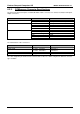
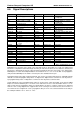
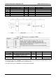
Signal Description I/O Termination Remarks
USB0 USB Port 0, data + or D+ I/O 3.3V USB 2.0 compliant
USB0# USB Port 0, data - or D- I/O 3.3V USB 2.0 compliant
to
USB7 USB Port 7, data + or D+ I/O 3.3V USB 2.0 compliant
USB7 USB Port 7, data - or D- I/O 3.3V USB 2.0 compliant
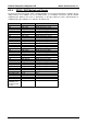
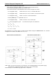
Signal Description I/O Termination
Remarks
LPC_AD[0-3] Multiplexed Command, Address and Data I/O 3.3V
LPC_FRAME# Frame: Indicates the start of a new cycle
or termination of a broken cycle
O 3.3V
LPC_DRQ[0-1]#
Encoded DMA/Bus Master Request. I 3.3V
I 3.3V PU 10k 3.3V
LPC_Reset# Reset# O 3.3V Generated from the
PCI_Reset# Signal.
Carrier Board LPC devices should be clocked with the LPC clock provided by the module interface. LPC
clock length guidelines are the same as those for the PCI clock.
Carrier Board LPC devices should be reset with signal CB_RESET#.