
User manual


Kontron Compact Computers AG SMX945 Detailed Manual V1.1
43
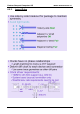
6.4. Signal Loss
COM Express™ module and carrier board insertion-loss budgets for the PCI Express, SATA, USB and GBE
interfaces are presented in the following sections.
These budgets were formulated to be compatible with the relevant source specifications. The source
specifications vary in their treatment of insertion-loss parameters. For example, the PCI Express Card
Electromechanical Specification factors cross-talk losses into the insertion-loss budgets, but the SATA, USB
and GBE source specifications do not.
There is no explicit COM Express™ jitter budget for the high speed differential interfaces. Designers should
refer to the relevant source specifications (PCIE, SATA, USB and GBE) for system jitter budgets.
For frequency-dependent material losses, a rule-of-thumb insertion-loss value of 0.28 dB per inch per GHz is
used in all cases, representative of commonly used FR4 PCB laminates. This value is consistent with the
PCI Express Card Electromechanical Specification usage (which calls out a 1.4 dB material loss for 4 inches
of trace at 1.25 GHz). It is also consistent with other PICMG
®
specifications that use values slightly above
and below this value.
Module and carrier board vendors may elect to use PCB laminates with better characteristics than common
FR4. If this is done, then the trace lengths referenced in the following sections may be extended as long as
the net insertion-loss budgets are met.
Loss budgets for future generations of PCI Express (Gen 2), Ethernet (10 Gb/s) and SATA (Gen 3) will be
addressed in future revisions to this document.