
User manual


Kontron Compact Computers AG SMX945 Detailed Manual V1.1
23
3.4. CMOS RAM Map
Systems based on the industry-standard specification include a battery backed Real Time Clock chip. This
clock contains at least 64Bytes of non-volatile RAM. The system BIOS uses this area to store information
including system configuration and initialization parameters, system diagnostics, and the time and date. This
information remains intact even when the system is powered down.
The BIOS supports 128Bytes of CMOS RAM. This information is accessible through I/O ports 70h and 71h.
CMOS RAM can be divided into several segments:
Locations 00h - 0Fh contain real time clock (RTC) and status information
Locations 10h - 2Fh contain system configuration data
Locations 30h - 3Fh contain System BIOS-specific configuration data as well as chipset-specific
information
Locations 40h - 7Fh contain chipset-specific information as well as power management configuration
parameters
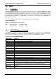
3.5. System Memory Map
The PENTIUM CPU, used as a central processing unit on the MICROSPACE, has a memory address
space which is defined by 32 address bits. Therefore, it can address 4GBytes of memory. The memory
address map is as follows:
CPU Pentium
Address Size Function / Comments
000000 - 09FFFFh 640kBytes Onboard DRAM for DOS applications
0C0000 - 0CBFFFh
0CC000 - 0CFFFFh
48kBytes
16kBytes
VGA BIOS, selected by the hardware
BIOS extensions, selected by the hardware
0D0000 - 0D4000h
0D4000 - 0D8000h
0D8000 - 0DFFFFh
16kBytes
16kBytes
32kBytes
Free for user
Free for user
Free for user
0E0000 - 0FFFFFh 1024kBytes Core BIOS, selected by the 945GM chipset
100000 - 1FFFFFh 1MByte DRAM for extended onboard memory
200000 - FFFFFFh 14MBytes DRAM for extended onboard memory