
User manual


DIGITAL-LOGIC AG MSM800SEV/SEL/BEV/XEV/XEL Detailed Manual V1.5
106
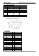
J16 Sound/Audio Port
Pin Signal Pin Signal
1 Input_CD_L 2 GND
3 Input_CD_R 4 Input_AUX_L
5 GND 6 Input_AUX_R
7 Input_Line_L 8 GND
9 Input_Line_R 10 GND
11 Input_MIC 1 12 GND
13 Input_MIC 2 14 Input Mono
15 Output Front / Line Left 16 GND
17 Output Front / Line Right 18 GND
19 Output Surround Left 20 GND
21 Output Surround Right 22 GND
23 Output_Center 24 GND
25 Output_Subwoofer 26 GND
27 SPDIF Digital Output 28 Jack Sense 0 Input
29 Jack Sense 1 Input 30 Jack Sense 2 Input
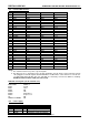
J17 10/100 BASE-T interface Connector
J17 Pin *
Signal
Pin 1 = TX-
Pin 2 = TX+
Pin 3 = RX-
Pin 4 = RX+
Pin 5 = Activity LED
Pin 6 = BAT input 3.0-3.6V
Pin 7 = GND
Pin 8 = VCC 3.3V
Pin 9 = Speed LED
Pin 10 = Link LED
At the J17, the LAN-Interface board including the LAN-Transformator and the Lithium RTC-Battery (for
backup) must be connected.