
User manual


DIGITAL-LOGIC AG MSM800SEV/SEL/BEV/XEV/XEL Detailed Manual V1.5
104
J12 IrDA Connector
Pin Signal
1 VCC
2 IRTX
3 IRRX
4 GND
BIOS settings:
You must enable the UART A of the GeodeLX in the BIOS setup:
F1Mother board device configurationI/O configuration:
UART port A = enabled
UART mode = SIR/CIR
Attention!
Never set the UART A mode to “Serial-16550 compatible” or “Extended” when an IrDA diode is
connected to the X44 or the diode will be destroyed!
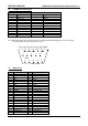
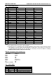
J13. Printer Port (Centronics)
The printer connector provides an interface for 8bit Centronics printers.
Header onboard D-SUB connector Signal
Pin 1 Pin 1 = Strobe
Pin 3 Pin 2 = Data 0
Pin 5 Pin 3 = Data 1
Pin 7 Pin 4 = Data 2
Pin 9 Pin 5 = Data 3
Pin 11 Pin 6 = Data 4
Pin 13 Pin 7 = Data 5
Pin 15 Pin 8 = Data 6
Pin 17 Pin 9 = Data 7
Pin 19 Pin 10 = Acknowledge
Pin 21 Pin 11 = Busy
Pin 23 Pin 12 = paper end
Pin 25 Pin 13 = select
Pin 2 Pin 14 = autofeed
Pin 4 Pin 15 = error
Pin 6 Pin 16 = init printer
Pin 8 Pin 17 = shift in (SI)
Pins 10, 12, 14, 16, 18 Pins 18-22 = left open
Pins 20, 22, 24 Pins 23-25 = GND