
Operating instructions

10 | MCO-5211
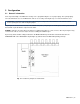
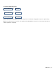
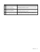
XLR connector panels
XLR connectors are used for output of the balanced signal channels of the changeover. These channels are only
available when the MCO-OPT-8618 option has been installed.
Each channel has two connectors:
• IN 1/2 9-pin D-sub carrying the inputs from the two MSG-5300 Master Sync Generators
Note: the MSG outputs are on XLR connectors. A special “Y” cable is provided to connect those
outputs to this connector.
• OUT XLR balanced output.
Fig. 4.4 XLR Connector panel (MCO-OPT-8618 Option)
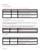
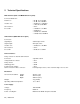
Remote Interface
The remote interface is of the TTL pull-down type, with a 9-pin male sub-D connector on the
rear panel.
The remote interface provides access to additional functions not available on the front of the
instrument.
Fig. 4.5 Remote Interface,
seen from rear
panel
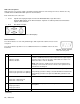
Pin
Function and Value
Comments
1 Input:
0: Remote enable
1: Remote disable.
-
Control function to enable remote-controlled operation if remote
control is enabled on the front of the instrument. The output signals
from the remote connector are active and indicate the status even
when the remote control is disabled.
Note: If the remote is enabled on the front of the instrument and
nothing is connected to the remote connector, the operation of the
instrument is unchanged.
2 Input:
0: Select sync generator 1 as primary
1: Select sync generator 2 as primary
Selects which sync source has been selected as the primary.
The primary generator is always selected "ON AIR" in manual mode.
The primary generator is the preferred "ON AIR" generator in auto
mode.
3 Input:
0:Selection of manual mode
1:Selection of auto mode
Selects if the switching is manual or automatic.
4 Output: "ON AIR"
0: Sync generator 1
1: Sync generator 2
Indicates which sync generator is being used, i.e. ON AIR on the
front panel.
5 Ground connection
(continued)