
Operating instructions

MCO-5211 | 9
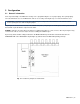
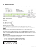
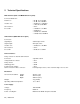
4.3 Rear Panel Connections
The figure shows the base unit with four BNC channels, and the positioning of factory-installed optional channels
when present.
Fig 4.2 MCO-5211 rear panel
Mains
Power switch:
ON: When "I" is pressed.
OFF: When "0" is pressed.
AC Power Connector & Fuse Holder
Use the supplied power cord, or an equivalent that meets the required standards for the country of use.
The mains fuse holder is located beneath the power cord socket. See page 3 for instructions on changing the fuse.
REMOTE
Connector for remote control of the changeover unit. The remote connector is of the ground closure type.
MSG-5300 1/2 (NB – may be labeled differently on some units)
Sync generator connector, used with a special cable to connect the two MSG-5300 Master Sync Generators in the
setup to the changeover unit. Which generator is SPG1 and which is SPG2 is defined by how this cable is connected.
The identification is printed on the cable connectors.
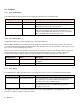
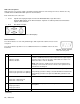
BNC connector panels
BNC connectors are used on all the unbalanced signal channels. The connectors are arranged in groups of three,
each identified by a number corresponding to the changeover channel. The standard unit includes the Channels 1 to
4. Up to 12 channels can be installed-in the form of optional units.
• IN1: Connector to be used for the signal from the SPG1 generator.
• IN2: Connector to be used for the signal from the SPG2 generator.
• OUT: Connector with the selected output from either SPG1 or SPG2.
Fig. 4.3 BNC Connector panel (Base unit, and MCO-OPT-8617 Option)