MCO-5211 Master Sync Change-over Guide to Installation and Operation M3006-9700-100 4 October 2013 Miranda Technologies 3499 Douglas-B.-Floreani St-Laurent, Québec, Canada H4S 2C6 Tel. 514-333-1772 Fax. 514-333-9828 www.miranda.
SAFETY COMPLIANCE This equipment complies with: nd EN 60950-1 (2 edition) directive 2006/95/EC nd CSA C22.2 No. 60950-1 (2 edition) nd UL 60950-1 (2 edition) The power cord supplied with this equipment meets the appropriate national standards for the country of destination. WARNING An appropriately listed/certified mains supply power cord must be used for the connection of the equipment to the mains voltage at either 120V~ or 240V~.
Table of Contents 1 2 3 4 5 Introduction and Applications ................................................................................................................................... 1 1.1 Introduction ....................................................................................................................................................... 1 1.2 Applications ............................................................................................................................
. How to contact us: For technical assistance, please contact the Miranda Technical support center nearest you: Americas 9:00 am – 9:00 pm EST Tel: +1 800 224 7882 Fax: +1 514 335 1614 support@miranda.com Asia 9:30 am – 6:00 pm GMT+8 Tel: +852 2539 6987 Fax: +852 2539 0804 asiatech@miranda.com Europe, UK, Middle East, Africa 9:00 am – 6:00 pm GMT Tel: +44 118 952 3444 Fax: +44 118 952 3401 eurotech@miranda.com France 9:00 am – 5:00 pm GMT+1 Tel: +33 1 55 86 87 88 Fax: +33 1 55 86 00 29 eurotech@miranda.
1 Introduction and Applications 1.1 Introduction The MCO-5211 Master Sync Change-over is designed to be used with a pair of MSG-5300 Master Sync Generators. The MSG-5300 is designed as a modular Sync Pulse Generator (SPG) which can be configured for use in all environments, from the smallest edit bay to the largest studio. The MCO-5211’s design complements this modular approach to ensure complete sync system reliability. The basic version of the MCO-5211 includes four channels equipped with 75.
1.3 Configuration The basic MCO-5211 Changeover includes four identical 75Ω channels with BNC connectors. Two available options, the MCO-OPT-8617 and MCO-OPT-8618, are used to add more channels to the changeover unit. • The MCO-OPT-8617 BNC option adds two additional 75Ω channels with BNC connectors, identical in functionality to the standard channels. • The MCO-OPT-8618 XLR option adds two balanced channels with XLR connectors.
2 Safety 2.1 Safety Characteristics This apparatus has been designed and tested in accordance with the Safety Class 1 requirements of IEC Publication 1010-1 ("Safety Requirements for Electrical Measuring Apparatus"), and is safe as supplied. This manual contains information and warnings which must be followed during operation and maintenance in order to ensure operator and service personnel safety. 2.
WARNING: Make sure that only fuses of the required rating, correct voltage, and the specified type are used for replacement. The use of repaired (jumpered) fuses and/or short circuiting of the fuse holder is prohibited. Fuses may only be replaced by a qualified person who is aware of the hazards involved. 2.5 2.5.1 Safe Access To and Replacement of Parts Safety The opening of covers or removal of parts, except those to which access can be gained by hand, is liable to expose live parts.
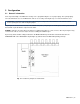
3 Configuration 3.1 General Information Some key functionality of the MCO-5211 changeover is programmed by the use of jumper plugs. These jumper plugs are located inside the case of the MCO-5211, and are accessed by removing the top cover of the instrument’s case. WARNING – opening the case may expose live wiring and components. DISCONNECT THE POWER CORD before opening the case and moving the jumpers. The jumpers are located on the left side of the Main Board (Unit 1).
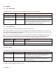
3.2 3.2.1 Jumpers PP1 - Audio Beeper The audible alarm can be programmed to three different functional modes using jumper PP1. Jumper position Status Description Center (factory default) OFF No connection Front FOLLOWS ALARM The beeper follows the alarm function and is reset together with this function from the front of the instrument Back FOLLOWS FAULT The beeper follows the fault indicators on the front of the MCO5211.
To reset the alarm relay, press: HOLD TO MODIFY plus MANUAL or HOLD TO MODIFY plus SYNC GEN. 1 or HOLD TO MODIFY plus SYNC GEN. 2 By choosing the mode already active, the alarm relay can be reset without changing the changeover signal routing. Note: The alarm cannot be reset if the error signal from the MSG-5300 is still active. It is not possible to disable the alarm relay function completely.
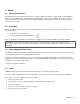
4 Operating Instructions Fig. 4-1 Front of the Instrument 4.1 Front Panel Indicators REMOTE A yellow LED that indicates that the unit is being controlled from the remote interface, not from the front panel. ON AIR Two green LEDs that indicate which sync generator is "on air". One (and only one) of the ON AIR indicators will be active at all times. FAULT Two red LEDs, each indicating that an error has been detected in the corresponding sync generator.
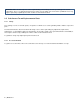
4.3 Rear Panel Connections The figure shows the base unit with four BNC channels, and the positioning of factory-installed optional channels when present. Fig 4.2 MCO-5211 rear panel Mains Power switch: ON: When "I" is pressed. OFF: When "0" is pressed. AC Power Connector & Fuse Holder Use the supplied power cord, or an equivalent that meets the required standards for the country of use. The mains fuse holder is located beneath the power cord socket. See page 3 for instructions on changing the fuse.
XLR connector panels XLR connectors are used for output of the balanced signal channels of the changeover. These channels are only available when the MCO-OPT-8618 option has been installed. Each channel has two connectors: • IN 1/2 9-pin D-sub carrying the inputs from the two MSG-5300 Master Sync Generators Note: the MSG outputs are on XLR connectors. A special “Y” cable is provided to connect those outputs to this connector. • OUT XLR balanced output. Fig. 4.
Pin Function and Value 6 7 Output Comments Error status flag for sync generator 1. 0: Fault on sync generator 1 1: No fault on sync generator 1 Note: During power failure in the changeover, pins 6 and 7 indicate fault on sync generators both 1 and 2. Output Error _status flag for sync generator 2 0: Fault on sync generator 2 1: No fault on sync generator 2 Note: During power failure in the changeover, pins 6 and 7 indicate fault on both sync generators 1 and 2.
5 Technical Specifications BNC Channels (Basic and MCO-OPT-8617 option) Connector: BNC 75 Ω Return loss: > 36 dB, 0.1 to 10 MHz > 15 dB, 10 to 360 MHz Insertion loss: < 0.2 dB, 0.1 to 180 MHz < 1 dB, 180 to 360 MHz < 0.2 Ω < -70 dB, 0.1 to 10 MHz < -80 dB at fsc < -50 dB, 10 to 180 MHz < -30 dB, 180 to 360 MHz On resistance: Cross-talk: XLR Channels (MCO-OPT-8618 option) Connectors: Signal input: Signal output: Insertion loss: On resistance: Cross-talk: Sub-D 9 pin, female XLR 3 pin, male < 0.4 dB, 0.