------------------------------------------------------------------------------------------------------------------------------------------------------------------------------------------------------------------------------------------------------------------------------------------------- MXS-EVO Disciplined RF Generator Rev 1.
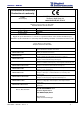
MXS-EVO - MANUAL Dichiarazione di conformità Declaration of conformity DIGITAL INSTRUMENTS S.r.l.
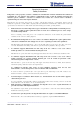
MXS-EVO - MANUAL Istruzioni di sicurezza Safety Instructions Il dispositivo è stato progettato, costruito e collaudato in conformità alle normative richiamate nel Certificato di Conformità ed è stato rilasciato dal costruttore completamente testato secondo gli standard di sicurezza. Per mantenere questa condizione e assicurare la sicurezza d’uso, l’utente deve osservare tutte le istruzioni e segnalazioni di pericolo descritte in questo manuale.
MXS-EVO - MANUAL Simboli di sicurezza Safety Symbols Sono presenti sul dispositivo e nella documentazione simboli utilizzati per la segnalazione di segnalazione conformi alle specifiche IEC61010-1 II. Safety-related symbols used on equipment and documentation comply with IEC 61010-1 II. • SIMBOLO DIRECT CURRENT IEC 417, N°5031 Vdc may be used on rating labels • SIMBOLO ALTERNATING CURRENT IEC 417, N°5032 For rating labels, the symbol is typically replaced by V and Hz as in 230V, 50Hz.
MXS-EVO - MANUAL MXS-EVO Disciplined RF Generator with Multiple Sources Index Summary ....................................................................................................................................................................... 6 Front View..................................................................................................................................................................... 7 Rear View ..................................................................
MXS-EVO - MANUAL Summary This manual provides to the user of the apparatus MXS-EVO all the information necessary for proper operation. The informations include the normal installation procedures and any data on the maintenance and programming in order to facilitate interventions in the field. MXS-EVO is a multiple output signal generator able to reconstruct stable time-frequency references (10MHz, PPS, 2.048MHz, E1, IRIG-B).
MXS-EVO - MANUAL Front View The front panel appears as shown in the following figure. On the left side there are the two removable modules, whilst on the right can be found an alphanumeric 20x4 display and a keyboard. PWR L PWR R GPS EXT E1 / T1 IRIG PTP Keyboard Alphanumeric Display In modo operativo sul display vengono visualizzati alcuni parametri come nell’esempio sotto: Device name Digital MXS-EVO Instruments 1.
MXS-EVO - MANUAL Connectors details TLS connector (Remote signals) 11 The 8 poles TLS connector provides the following information on the various pins (from left to right): PIN 1: Common contact PIN 2: Closed contact Right power supply provided PIN 3: Closed contact Left power supply provided PIN 4: Closed contact GPS reference present and valid PIN 5: Closed contact EXT reference present and valid PIN 6: Closed contact E1 reference present and valid PIN 7: Closed contact PTP reference present
MXS-EVO - MANUAL Four connectors have fixed functions that cannot be altered: Twelve connectors have instead customizable functions by means of a DIP switch matrix placed on the PCB inside the device: Even if modifying the outputs is simple is suggested to first contact the factory in order to avoid voiding the warranty by opening the device.
MXS-EVO - MANUAL Main Operation The main purpose of the MXS-EVO is to provide stable output signals of Time (PPS, E1, IRIG code, NTP/PTP) and Frequency (10 MHz, 2.048MHz), and to enable the synchronization of the network. This is allowed by the application of algorithms, tuning an high-stability internal oscillator. Peculiarities of the ETS-EVO is the possibility to accept input from four different sources: 1. GPS 2. EXTERNAL REFERENCE 3. E1 4. PTP (IEEE 1588) 5.
MXS-EVO - MANUAL is widely used in digital telecommunications worldwide, with the exception of USA and Canada (where the T1 signal is in use) and Japan (where is in use the J1). The E1 link operates on two separate coaxial cables (Rx and Tx). Also in this case it’s possible perform a rapid frequency locking with the 2.048 MHz reference of E1 signal, setting the Disciplining Mode voice to the frequency value.
MXS-EVO - MANUAL Error Rate Test (in reception and / or transmission), and choosing which of timeslots (except for the one used for the PPS and, advising against the first, where the sync data are sent) to receive and / or send the signal for the test. The form of the Bit Error Rate Test can generate and detect pattern both pseudo-random and repetitive. It’s used to test and stress the channels of communication data. Has been set the pseudo random pattern QRSS for testing.
MXS-EVO - MANUAL PTP (IEEE 1588) The MXS-EVO supports the IEEE 1588-2008 (version 2), also known as Precision Time Protocol, both as master and slave. When connected to an appropriate device compatible to the IEEE 1588 standard is able to synchronize the slave apparatus with a precision well below the micro-second.
MXS-EVO - MANUAL IRIG-B The device can accept in input and provide in output (on BNC and optical connectors) an IRIG-B stream of type 006, compliant with following code: ------------------------------------------------------------------------------------------------------------------------------------------------------------------------------------------------------------------------------------------------------------------------------------------------- MXS-EVO – Manual – Rev 1.
MXS-EVO - MANUAL It was also implemented part of the standard 1344-1995. The offset compared to the UTC time can be set using the Timezone of the apparatus. Changes of DST or leap second are not currently notified (always returned as 0). The device can output both an IRIG-B DCLS and IRIG-B AM signals. It can also recognize an IRIG-B DCLS signal via a BNC or optical connector. When the BNC connector is used it inhibits the external timing input.
MXS-EVO - MANUAL Switchover Function ETS-EVO allows the possibility to switch the disciplining of its internal timebase selecting one of many sources.
MXS-EVO - MANUAL Characterization of Sources MXS-EVO was also designed to compare the quality of the different sources provided to apparatus, analyzing the ratio ∆f / f (variation of the frequency value on the nominal frequency) of each source. This analysis is supported by a graph (that can be generated by the Stability Chart button in the Main Panel) which shows the trend of these ratios over time. The step used is 5 minutes, while the values are expressed in nanoseconds.
MXS-EVO - MANUAL It is also possible display the progress of these distances over time (using the button Distance Chart in the Main Panel). ------------------------------------------------------------------------------------------------------------------------------------------------------------------------------------------------------------------------------------------------------------------------------------------------- MXS-EVO – Manual – Rev 1.
MXS-EVO - MANUAL Graph Menu The graph menu can be navigated with the pressing of the four direction provided by the keyboard. UP LEFT (Escape) RIGHT (Enter) DOWN To enter the first level from level zero (ROOT) is enough to press the RIGHT key, that works as Enter key. At this point all the first level menus are visible in a cyclic loop with the pressing of the UP and DOWN keys. The currently selected menu is recognized by an arrow placed on its left side.
MXS-EVO - MANUAL In the following table the whole graph is shown, with the associated permitted values for each parameter.
MXS-EVO - MANUAL Frequency Ref. EXT Time Ref.
MXS-EVO - MANUAL WEB Interface The MXS-EVO is managed by the network using a common browser by simply connecting to the associated IP address. Mode Menu Local/Remote In local mode is only possible to modify operative parameters from the front panel display. In remote mode it can be done from WEB, SNMP and REMOTE CONTROLS. In the WEB interface this value is visible in the Remote Mode Status field. When Disabled is shown no operation can be made to change the operative status of the apparatus.
MXS-EVO - MANUAL Board Config Panel Source Permits to force a switch on a different source when the device is configured in manual switch mode. To switch from the WEB interface just go the the View tab of the Main Panel and click on a source. Manual/Auto Allows to set the type of switching (manual or automatic). Disciplining Mode Selects the kind of tuning to use when discipling from da EXT or E1 reference. The frequency tune is faster, but loses the phase alignment of the PPS provided in output.
MXS-EVO - MANUAL Board Status Overview Permits to view the status of all the sources alongside their time reference cvomparison with the internal reference. Info Displays the name of the device and the corresponding software release. The ID field can be customized by the user to track the device. These informations are displayed in the Board Info panel of the main page of the WEB interface. Disciplining Shows the current disciplining value given to the internal oscillator and the synchronization status.
MXS-EVO - MANUAL GPS Status Displays some informations about the GPS radio. If present and its time delay in respect to the internal PPS. Positioning Mode Permits to set the way in which the GPS module should calculate its geographical position. If extract it from the information collected from the satellites or using the one given by the user. The “Altitude Hold” mode may not be available on every GPS module. Latitude Permits to view/set the latitude of the GPS antenna.
MXS-EVO - MANUAL The satellite view can be opened by pressing the Polar view button. EXT Frequency Ref. It allows to display the frequency reference, expressed in Hz, which is currently supplied as an input to the apparatus and if this value has been accepted. Its acceptance or not depends on the value set as acceptable and on tolerance (viewable by pressing ↓). Time Ref.
MXS-EVO - MANUAL These values are configurable by the GPS / EXT / PTP Config Panel. E1 For informations concerning the E1 status variables, see paragraph "E1" and specifically subsections "status information" and "settings available." In the web interface it’s possible view the values of state variables of the settings in Tab E1 of the Main Panel, while is possible change the settings on the E1 Config Panel.
MXS-EVO - MANUAL PTP The PTP settings are split across two panels. The in-depth configuration is carried on in the Advanced panel, whilst the basic settings can be directly changed from the Sources Panel. Enable Allows to switch on or off the PTP. Type Allows to choose to configure the device as a Grandmaster or a Slave.
MXS-EVO - MANUAL Profile Allows to choose to choose between some predefined profiles for common configurations. Multicast/Unicast Allow to choose the type of communication mechanism. IP Dest Allows to define a series of additional unicast addresses. Advanced Allows to configure a set of advanced settings. Intervals The various interval values are expressed in power of 2, so 0 corresponds to 1 second, 1 to 2 seconds and -1 to 0.5 seconds. VLAN Allow to enable or disable the 802.1Q protocol.
MXS-EVO - MANUAL Event Log On the WEB is available the apparatus log from Event log section. 50 entries are presented. It is possible to delete the logs and save them in csv. format.
MXS-EVO - MANUAL SNMP Trap Management For each event related to the board, is generated a trap in parallel parallel to the machine set under TrapDest. The trap number reflects the event number and the contents of the SNMP variable associated contains the details (for example, the channel referred to the event). User Account The main user who has access to the apparatus is the administrator. He is able to change its credentials under Account Settings.
MXS-EVO - MANUAL Custom Settings The device permits to have some ad-hoc customizations through the unlock with particular activation codes. Pulse Generation The device is able to generate a programmable pulse in place of the IRIG-B DCLS signal (on the BNC connector) or the PPS signal. The following parameters can be set: HH:MM:SS HH:MM:SS MM:SS SS.
MXS-EVO - MANUAL First Run First Installation 1. 2. Connect at least one of the possible sources (GPS, EXT, E1, PTP, IRIG-B) in the following way: • GPS: connect the GPS antenna cable to the proper GPS ANTENNA socket on the rear. • EXT: connect a frequency or time reference on the proper connector on the rear. • E1: connect an E1 connector on the proper input socket on the back.
MXS-EVO - MANUAL The default credentials are: administrator (read and write) guest (read only) admin / admin guest / guest From here, it’s possible to check: • • • • • • Presence of the GPS antenna In the GPS tab of the Main Panel the Antenna led should be green and, after a few minutes from the boot, the PPS Status led should become green, too. Presence of the Ext. Frequency signal In the Ext tab of the Main Panel the Valid led of the Frequency box should be green.
MXS-EVO - MANUAL Appendix A: Quality Factor General Review This appendix is intended to illustrate the meaning and motivation of the introduction of the Quality Factor within the Digital Instruments equipments. Although the installation of a GPS device is relatively easy, it can hide certain issues that in some cases it can affect the proper functioning. It is therefore expected to monitoring certain operating parameters so as to make immediate validation of a Circuit or finding the source of any problems.
MXS-EVO - MANUAL It’s possible get an idea of potential obstacles that limit the visibility of the GPS constellation to the radio observing the polar graph of satellites after a few hours of persistence. Quality Factor Quality Factor is the operating parameter that indicates the quality of the GPS signal received by the antenna. It is considered an acceptable value if > 25. If the Q.F.
MXS-EVO - MANUAL Statistics The device stores some useful statistical informations to evaluate the proper functioning over time: Holdover Num Holdover Max Quality Min PPS Dist Max Pos Alarm Num shows the number of times that the GPS radio has entered into holdover mode in response to a problem (under optimal conditions should be low) shows the duration of the longer hold-over (under optimal conditions should be low) indicates the smallest GPS antenna quality factor recorded (under optimal conditions shoul
MXS-EVO - MANUAL Appendix B: FAQ D: How is it possible to certify the various time references? R: In order to certify a particular reference is better to have the device disciplined by GPS or from another stable source. In this way is possible to evaluate the jitter of the reconstructed PPS in different ways: 1. by asking the device the log of the last 6 hours http://x.x.x.x/cgi-bin/savestability 2. by letting an external event logger collect the data (e.g. AON Console Manager) 3.
MXS-EVO - MANUAL Press the Save Screen button and specify a file on which to save the data. The acquisition is now started and ends when the utility is closed. If the Continuous save field is not enabled is possible to press Save Screen in order to save the data currently acquired (it may slow down the PC if there is much data to save). The resulting file is a simple csv that may be edited and viewed by a commond spreadsheet program (e.g. Microsoft Excel).
MXS-EVO - MANUAL The schematic is depicted here: ------------------------------------------------------------------------------------------------------------------------------------------------------------------------------------------------------------------------------------------------------------------------------------------------- MXS-EVO – Manual – Rev 1.
MXS-EVO - MANUAL Appendix C: Changelog Release 1.0 (december 2011) • First release Release 1.1 (february 2012) • Added support for IRIG-B Release 1.2 (march 2012) • Added support for Synchronous Ethernet Release 1.3 (april 2012) • Enhanced disciplining of the NTP server Release 1.4 (june 2012) • Enhanced recognition of the external frequency • Added support for hardware upgrade Release 1.
MXS-EVO - MANUAL Release 2.7 (september 2013) • Added multiple VLAN support Release 2.8 (october 2013) • Added support for NTP hardware timestamping Release 2.
MXS-EVO - MANUAL Assistance For support requests please download the form from the website: http://www.digital-instruments.it/ita/assistenza.php Compile it in its entirety by specifying as precisely as possible and giving as many details as possible about the type of fault detected. You can then send the form to riparazioni@digital-instruments.com, via fax to +39.02.66506103, or enter it directly into the box when sending goods for repair. You can also contact us at +39.02.
MXS-EVO - MANUAL Technical Data Programmable outpts Outputs Signals Output impedance Output connector Frequency Reference Signal Spectral Purity Phase noise Output level Output impedance Output connector Stability 12 PPS, IRIG-B DCLS, IRIG-B AM, E1, 2.048 MHz, 10 MHz 50 Ω BNC 10 MHz sine wave, 2.
MXS-EVO - MANUAL < 100 ns with hardware timestamping (disables PTP) IRIG Section Format Modulation Frequency Information sent Connector B Pulse width modulated / Amplitude modulated DC / 1 KHz TOY (BCD), Year (BCD) BNC (electrical) or ST (optical 850 nm multimodal) Signaling Network connection Signaling Serial Connection Remote signalling Remote controllers N° 1 Ethernet 10/100 interfaces, TCP/IP protocol N° 7 led on front panel RS-232 connector DB9 Male +/- 15 kV (ESD) 7 Dry contact on Weidmuller connec