
User manual


Blackfin DEV-BF548-Lite. DEV-BF548DA-lite Hardware User Manual
16
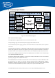
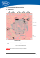
4.9 Expansion Connectors
The interface to the extender boards is grouped into three different connectors (X1, X2, X3). The three
tables below shows the pin out of these three connectors. The column “Pin No. (Connector)” shows the
pin number of each connector, while the column “Pin No. (Symbol) shows the pin number of the
extension connector schematic symbol, where the pins are numbered from 1 to 200. The column “Pin
No. CM” represents the pin number of the corresponding signal on the Core Module.
4.9.1 X2 – Expansion Connector 2
Pin No.
(Symbol)
Pin No.
(Connector)
Signal Signaltype PinNoCM
1 1 PC7 I/O 93
2 2 PC6 I/O 94
3 3 PC3 I/O 97
4 4 PC2 I/O 98
5 5 CLKOU
T
O 70
6 6 PE15 I/O 185
7 7 PA13 I/O 114
8 8 PA5 I/O 106
9 9 3.3V PWR
10 10 3.3V PWR
11 11 PD0 I/O 135
12 12 PD2 I/O 137
13 13 PD4 I/O 139
14 14 PD6 I/O 141
15 15 PD8 I/O 143
16 16 PD10 I/O 145
17 17 PD12 I/O 147
18 18 PD14 I/O 149
19 19 PH0 I/O 22
20 20 PE12 I/O 188
21 21 PB11 I/O 130
22 22 PB9 I/O 128
23 23 PE8 I/O 192
24 24 PB13 I/O 132
25 25 PB12 I/O 131
26 26 PH1 I/O 23
27 27 nARDY I 21
28 28 PH4 I/O 26
29 29 5.0V *) PWR
30 30 5.0V
2
) PWR
31 31 Vin
3
) PWR
32 32 Vin
3
) PWR
33 33 PH7 I/O 29
34 34 nAMS3 O 32
35 35 nABE1 O 17
36 36 nABE0 O 16
37 37 PB14 I/O 133
38 38 PE7 I/O 193
39 39 PB8 I/O 127