
User manual


Blackfin DEV-BF548-Lite. DEV-BF548DA-lite Hardware User Manual
11
3 PCB Placement and Mechanical Outline
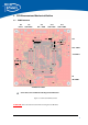
3.1 PCB Placement
Figure 3-1: Connector PCB Placement
ATTENTION:
Please mind the direction while inserting the Core Module!
S3
1
X8CAN0
X 5
Powe
r
1
1
80
X11
USB -UART
X 7
USB JTAG
X6
Ext . JTAG
0 1
S 2
J
P
1
S 4
X9
SD-CARD
X12
1 … 8
1 … 4
3131
41
30
60
30
60
40
X10 CAN 1
J
P
2
J
P
3
X2X 1
X3
X4 Ethernet JACK
X13
USB -OTG
S5
S 1
ON
Corner holes on Core Module indicating insertion Rotation
1
0
0
1
1
1
JP4