SATEL MR-1000 Self-controlled hot standby redundant master User guide version 1.3 P.O.Box 142, FI-24101 SALO, Finland Street: Meriniitynkatu 17, FI-24100 SALO, Finland Tel +358 2 777 7800, Fax +358 2 777 7810, E-mail info@satel.com www.satel.
MR-1000 user guide V1.3 TABLE OF CONTENTS TABLE OF CONTENTS .......................................................................................................................... 2 1. INTRODUCTION............................................................................................................................. 3 1.1. MR-1000 features ................................................................................................................ 3 1.2. MR-1000 technical specifications ........
MR-1000 user guide V1.3 1. INTRODUCTION SATEL MR-1000 redundant master is designed for enhanced reliability in critical VHF / UHF radio modem networks. SATEL MR-1000 features an automatic redundant controller with two radio transmitters and up to four receivers (depending on configuration) operating in hot standby redundant mode. The redundant configuration of MR-1000 secures the communication even if a failure occurs in one of the transceivers or power supplies.
MR-1000 user guide V1.3 1.3. SATEL radio modems available for MR-1000 installation Technical specifications: Frequency range Tuning range Channel spacing Carrier power NMS Diversity 1.4. SATELLINE-3AS VHF 135 ... 174 / 218 ...238 MHz 135 ... 155 / 138 ... 160 / 155 ... 174 / 218 ... 238 MHz 12.5 / 25 kHz fixed 0.1, 0.5, 1 and 5 W / 50 ohm Yes - SATELLINE-3AS NMS 330 ... 470 MHz +/- 2 MHz from central frequency 12.5 / 20 / 25 kHz fixed 0.01 ... 1 W / 50 ohm Yes - SATELLINE-3AS Epic NMS 330 ...
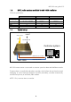
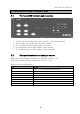
MR-1000 user guide V1.3 2. INDICATORS AND CONNECTORS 2.1. 1. 2. 3. 4. 5. 2.2. Front panel LED indicators and connectors On/Off –led indicates auto switch status. Led On = Auto switch activated Main/standby –led indicates the active radio modem.
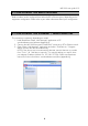
MR-1000 user guide V1.3 3. CONFIGURING THE RADIO MODEMS Radio modems can be configured from either the RS or Ethernet ports, depending on the equipment configuration. Please refer to your order information about your configuration. 4. CONFIGURING THE ETHERNET / SERIAL ADAPTERS This connection is optional, depending on model. 1. Install Brainboxes “Boost. LAN Manager” application to PC. www.brainboxes.com/software (Appendix A) 2.
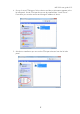
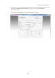
MR-1000 user guide V1.3 4. Set-up of virtual COM-ports. Select a device and device information appears to the left side panel. Virtual COM port drivers can be installed from “Install Device“. From there you can also rename and change IP-address of device. 5. After device installation you can see the COM port selection from the left side panel.
MR-1000 user guide V1.3 6. After steps 1-5 it is possible to configure the Ethernet/Serial adapters using your web browser (for example: Internet Explorer, Firefox etc.). Default IP address is 192.168.127.254. NOTE! Please see Brainboxes manual for further information.
MR-1000 user guide V1.3 5. ETHERNET PORTS ENABLED 5.1. RJ45 DATA port configuring SaTerm: 1. Download SATEL SaTerm software at download page: www.satel.com/userData/satel/downloads/software/SaTerm_sw_v4_3_5.zip 2. Install downloaded terminal program. 3. Choose the radio modem you want configure by pressing the MR-1000 front panel MANUAL button; the main/standby leds indicate the selected radio modem. Selecting the active radio modem is also possible with remote modem switch, see page 10. 4.
MR-1000 user guide V1.3 6. RS-232 PORTS ENABLED Please note: Not available simultaneously with Ethernet ports. 6.1. Data 1-port 6.2. Data 2-port: 6.3. NMS 1-port 6.4. NMS 2-port Connect the DATA1 port (RS-232, D9 female) to a PC. Select the modem to be configured by pressing the “Manual” switch in the MR-1000 front panel. Make the configuration as described in the corresponding SATELLINE radio modem manual by the use of the SaTerm terminal program and SL-commands. Check the status from the LEDs.
MR-1000 user guide V1.3 7. ADDING A MASTER STATION TO YOUR NETWORK See “SATEL NMS PC User guide” section 6.2.4: “Setting up a redundant master modem”. 8. CONFIGURING THE CONTROLLER The controller configuration is done from the front panel serial port marked “Config”. The terminal program (SaTerm) port settings should be 57600 bps 8, N, 1. The programming menu becomes available when letter C is sent to port. The settings are saved and the configuration menu exits when letter E is sent to port. 8.1.
MR-1000 user guide V1.3 9. FORCED MODEM SWITCH Forced switching of the active radio modem is possible locally from the “Manual” switch in the MR-1000 front panel. To force switch the active radio modem remotely, see the following instructions. Connect to the MR-1000 RJ45 NMS port, using IP address. The switching is forced by using MODBUS commands to virtual port 2 (COM port) by a terminal program. To trigger the manual remote switch both of the commands (ref. Command table below) needs to be sent (ON/OFF).
MR-1000 user guide V1.3 10.2. Windows PC set up 1. Download VirtualBox application from here (Appendix A): www.virtualbox.org/wiki/Downloads 2. Change PC network adapter connected to RS/ETH Link IP-address from “Control Panel\Network and Internet\Network Connections”. Use static IP address 192.168.7.10 and subnet mask 255.255.255.0. NOTE! The adapter should be in same subnet with RS/ETH Link which default IP is 192.168.7.1 10.3. VirtualBox installation 1. 2. 3. 4.
MR-1000 user guide V1.3 10.5. Create Virtual Machine with VirtualBox application 1. Open VirtualBox Select ”New” ”Create Virtual Machine” view appears 2. Write name ”XR7_GUI”, choose ”Linux” and version ”Debian (32 bit)” Press Next 3. Select memory size. Recommended size is 512 MB which would be enough. Press Next 4. ”Use an existing hard drive file” 5. Press and select “xr7-gui.vdi” file from here “C:\Program Files\Oracle\VirtualBox\xr7-gui.vdi”. Press Open 6. Press “Create” 7.
MR-1000 user guide V1.3 17. Virtual machine is fully started when terminal window prints “xr 7 login”, see picture 4 below. NOTE! Don’t close this window! 10.7. RS/ETH Link XR7 GUI settings Before you can test connection, remember connect power- and Ethernet cables to MR1000 controller. RS/ETH Link Ethernet port is connected to MR-1000 “Data” Ethernet port, RJ45f, picture 2. Picture 2 RS/ETH Link starts about 50 seconds. After that, test connection with “cmd ping command”. RS/ETH Link default IP is 192.
MR-1000 user guide V1.3 IP address: 192.168.7.1 Picture 6 10.8. Interface settings After login XR7-GUI front page appears. Press “Configure” to setup access. Select “Interface” press “CE01” button to IP address change. NOTE! For further information for any function of the RS/ETH Link, please press button, picture 7.
MR-1000 user guide V1.3 In “Configure” selection, change IP address if necessary. After that press “Apply”. NOTE! Remember change network adapter IP address to same subnet as RS/ETH Link. After that, renew the login with implemented IP address. FOR EVERY PERMANENT CONFIGURATION SAVE: Remember press “Save configuration” in status view. DNP3 polling is enabled in picture 8. Picture 8 10.9. Serial port settings To change Serial port settings press “Configure Serial port”.
MR-1000 user guide V1.3 Serial Port Settings changeable parameters are: Speed, Parity, Data bits, Stop bits, Flow control, DCD (data carrier detect) Picture 10 10.10. Gateway - Serial to Serial function It is possible to bridge data from serial port to another serial port. First select “SerialSerial”. Next select the data input serial port (for example S01_RS bridged to port S04). It is also possible to change data protocol mode (raw, dnp3).
MR-1000 user guide V1.3 10.11. Gateway - Serial to IP function In Serial to IP mode it is possible to bridge data between serial port and IP-port. First select “Serial-IP” and then select serial port which is data in and/or out port. Picture 12 After port selections the “Serial-IP Gateway Settings” scene appears where you can select protocol mode (dnp3, raw), IP type, IP port address and TCP port address (IP Configuration: Port). In client type it is necessary to define the correct TCP port.
MR-1000 user guide V1.3 10.12. Administration It is for example possible to change login password in Administration User management. Other functions in “Administration” selection are: Factory settings: To return default factory settings if necessary Firmware upgrade: For FW upgrade from a file or from a remote location (OTA) NOTE! For further information about Firmware upgrade, press -button and RS/ETH FW release. Before “Upgrade from a Remote Location” function, install TFTP server to your system.
MR-1000 user guide V1.3 11. MR-1000 INSTALLATION TO A RACK CABINET Option 1: Prepare the rails or slides into your rack cabinet. This is the preferred choice due to the weight of MR-1000. Side slides make service operations easier. NOTE! The slides are not included in MR-1000 delivery. Option 2: Use “Rittal ATX Economy RAID” telescope slides (Appendix A). NOTE! The slides are not included in MR-1000 delivery. 1.
MR-1000 user guide V1.3 12. SERVICE OPERATION: REPLACING A RADIO MODEM The radio modems in MR-1000 are easy to replace, also when the unit is operational. For this the external cabling must remain connected during the operation. (Using the slide rails in cabinet assembly makes the in-operation service easier.) 1. Use the “Manual” switch to switch off the radio modem to be replaced. Verify the state from the “Main/Standby” LEDs. 2. Slide the MR-1000 out from the cabin rack.
MR-1000 user guide V1.3 4. Remove the four screws from the modem mounting slot. 5. Detach the antenna connector. 6. Take out the radio modem 7.
MR-1000 user guide V1.3 8. Place a new radio modem in the slot. Execute instruction items 1 to 7 backwards. NOTE! Remember to configure the radio modem before placing it into MR-1000. This allows you to start automatic controlling immediately after installations, without a break in the network operation. 9. Slide the MR-1000 back to the cabin rack. 13.
MR-1000 user guide V1.3 Example: Main modem programming mode ON: Double click the correct flashupdate.exe. The following view appears. 5. Choose the COM port connected to modem “DATA” port. (Example used above: COM11). 6. After the correct port selection, select the “Flash”-button, FW update begins. 7.
MR-1000 user guide V1.3 14. ASSEMBLY AND CABLING FIGURE 14.1. Part 1 Mechanical assembly Name QTY Part Name QTY 19" Subrack, 3U 1 27 Hexagon socket screw DIN 912 1 3 TELESCOPIC SLIDES 800mm ENCLOSURES Back panel 4 Front panel 2 28 1 29 1 30 Hexagon socket screw DIN 912 2 16 8 6 Mounting clip 4 32 Hexagon socket screw DIN 912 A4 Set screw DIN 913 A4 M3x6 7 Tapping screw ISO7049 ST3.
MR-1000 user guide V1.3 14.2.
MR-1000 user guide V1.3 15. APPENDIX A 1. Brainboxes web page: http://www.brainboxes.com/software 2. Brainboxes docs: http://www.brainboxes.com/docs 3. SATEL programs and guides: Saterm: http://www.satel.com/userData/satel/downloads/software/SaTerm_sw_v4_3_5.zip SATEL NMS PC user guide: http://www.satel.com/product/satel-nms-pc-software Modem FW download page: http://www.satel.com/support/downloads/firmware 4. Putty: http://www.chiark.greenend.org.uk/~sgtatham/putty/download.html 5.