
Specifications


"ul~i
Slave
Product
Re£erenca
Manual
Appendix
H
DUAL
ASYNCHRONOUS
RECEIVER/TRANSMITTER
(OUART)
SCN2681
SERIES
AC",I:4)-CountedTlmor
Mode Mel
Clock
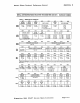
Table 4 ACR
[6:4)
FIELD DEFINITION
Source Select -
This
field
lelects
the
oper.tlng
mode
0'
the
counter/timer
.nd
itl
clock
source
.1
ahown In
t.ble
...
ACRP:OJ
- IP3, IP2.
1P1,
IPO Chlnoa
of
lletelntemapt
Enable - Thla field
"Iects
which
bltl
of
the
Input
Port
Ch.nge
regis·
te,
(lPCR) cause
the
Input change
bit
In
the
Interrupt
at.tul
reg later (ISR[7})
to
be
let.
I'
•
bit
la In
the
'on'
It.te,
the
setting
of
the
corresponding
bit
In
the
IPCR
will
allo
relult
In
the
letting
of
ISR(7),
which
rHult1
In
the
generation
of
.n
Interrupt
output
If
IMR[7}-
1.
If
a
bit
Is
in
the
'off'
It.te,
the
letting
of
th.t
bit
in the IPCR
hal
no
effect
on
ISR[7}.
IPeR - Input Port Change
Regllt.r
IPCA(7:.) - IP3. IP2, IP1,
IPO
Ching.
of
8tlt,
- These
bitl
.re
set
when.
change
0'
...
te, as defined In the
Input
Port sec·
tion
of
thil
data
Iheet,
occurs
at
the
reo
lpec:tlve
input
pin
•.
They
.re
cleared when
the
IPCR Is
re.d
by
the
CPU, A read
of
the
IPCR .110 clears ISR(7), the Input change
bit
In
the
Interrupt
.tatus
register.
The
lilting
of
theae
bits
can be program·
med
to
gener.te
.n
Interrupt
to
the CPU.
IPCR[3:0)
-IP3,IP2,IP1,IPO
Current
St.t.
- These
bits
provide
the
current
state
of
the
respective Inputs. The
Inform.tion
Is
unl.tched
.nd
reflects the state
of
the
in,
put
pins
at
the
time
the IPCR
is
read.
ISR - Interrupt
StatuI
Register
This
register provides the
status
of
all
potential
interrupt
sources. The
contents
of
this
register are masked
by
the
interrupt
mask register (IMR).
If
a
bit
In the ISR
is
a
'1'
.nd
the correspond
inc
bit in the IMR
i~
• Iso a '1', the INTRN
output
Will be
a~·
.erted.
If the corresponding
bit
in the IMR
i
••
zero, the state
of
the
bit
in the ISR has
no
effect
on
the
INTRN
output.
Note
that
the
IMR does
not
mask the reading
of
the
ISR -
the
true
Itatus
will be provideo
reg.rdless
of
the
contents
of
the IMR. The
contents
of
this
register are initialized to
00
16
when the DUAAT
is
reset.
ISRI1l-
Input
Pori
Chan",
St.tul
- This
bit
is
• '1' when a change
of
state
has·
occurred
.t
the
IPO,
IP1, IP2,
or
IP3
inputs
.nd
th.t
event has been selected
to
cause
.n
interrupt
by
the
programming
of
ACR(3:0). The
bit
il
cleared when the CPU
r
••
ds
the IPCR.
ACR(S:")
MODE
CLOCK SOURCE
000
Counter External (lP2)
001
Counter
TXCA -
lX
clock
of
ch.nnel
A
tr.nsmilter
010
Counter
TXCB.-
1X
clock
of
ch.nnel
B
transmitter
o 1 1 Counter
Crystal
or
external
clock
(Xl/CLK)
divided
by
16
1
00
Timer
External
(lP2)
1
o 1
Timer External
(lP2) divided by
16
1 1 0
Timer
Crystal
or
oxternal
clock
(X1/ClK)
1 1 1
Timer Crystal
or
oxternal
clock
(X1/ClK) dividr:d
by
16
ISRIS) - Channel a
Changl
In a .... k -
This bit, when set, indicates that the
chan·
nel
B receiver has detected the beginning
or
the end
of
a received break. It
is
roset
when the
CPU issues a channel B 'reset
break change Interrupt' command.
ISRIS) -
Ch.nnel
a
Recllver
Rudy
or
FIFO
Full
- The
function
of
this
bit
is pro·
grammed by MR1BI6].
ILprogrammed
as
receiver ready,
it
indicates that a character
has been
received .in channel B and is
waiting
in
the
FIFO
to
be read by the
C~U.
It
is
set when the character is transferred
from
the receive
shift
register to the FIFO
.nd
reset when the CPU reads the RHA.
If
after
this
read there are more characters
still
in the FIFO the
bit
Will be set again
after
the FIFO
is
'popped'.
If
programmed
as
FIFO full,
it
is set when a character is
transferred from the receive holding
regis·
ter
to
the receive FIFO and the transfer
causes the channel B
FIFO
to
become full,
i.e,
all three FIFO
positions
are occupied.
It
is
reset when the CPU reads the RHA.
If
a character is waiting
10
the receive
shift
register because the FIFO
is
lull,
the
bit
will be set _aain when the Wi/ltinO charac·
ter is loaded
into
the FIFO .
ISRI") - Channel a Transmitter
Reidy
-
ThiS
bit
is a duplicate
of
TxRDYB (SRBi2]I.
ISRI3)
- Counter
Rlady
- In the counter
mode,
this
bit
is
sel when the
counler
reaches terminal count and is reset when
the counter is stopped by a stop counter
command.
In the timer mode.
this
bit
IS
set once eact-
cycle
of
the generated square wave levery
other
time
that the counter/timer reaches
zero count) The bit
IS
reset by a stop
counter
command. The command,
hOoN'
ever, does not Slop the counterltimer.
ISR(2) - Channel A Change
In
a .... " -
This
bit, when set, indicates that the chan·
nel A receiver has
detectej
the beginning
or
the end
of
a received break.
It
is
reset
when the CPU issues a channel
It.
'roset·
break Change
Interrupt'
commanD.
ISRI')
- Channel A
Recllver
Rudy
or
FIFO
Full-
The
function
of
thiS
bit
is
pro-
grammed
by
MR1A[6J.
If
programmed
.s
receiver ready,
it
indicates that a character
has been received in channel A and
is
waiting
in
the
FIFO
to
be read
by
the
CPU.
It
is set when
the
character
is
transferred
from the receive
shift
register
to
the
FIFO
and reset when the CPU roads
the
AHR.
If
after
this
read there are
more
characters
still
in the FIFO the
bit
will
be set .g.1O
after
the FIFO
is
'popped'.
If
progr.mmed
as FIFO full. it
IS
set when a character is
transferred from the receive
holding
regis·
ter
to
the receive FIFO and the transfer
causes the
Cha'lnel A FIFO
to
become full,
I.e., all
three FIFO
positions
are occupied.
It
is
reset when the CPU reads
the
RHA.
If
a character is
waiting
In the receive
shift
reQlster because the FIFO
IS
full,
tne
bit
will
be
set again w
...
en the wa,tlnc; charac·
te~
IS
loaded Ir.to the FIFO
ISRIO]
- Channel A
Tr.nsmittlr
Rlady
-
This
btl
is a
duplicate
of
TxRDl'A
tSRAt2)'.
IMR - Interrupt Mask Register
The programming
of
this register selects
which
bits
in
the ISR cause
l"l
interrupt
output.
If a bit in the ISR
IS
a
',.
and the
corresponding
bit
in the IMR
IS
also a
T.
the It'HRN
output
wlii
be
a!>sertec
"the
corresponding
bit
In the
IM~
is a z(:'o, the
state
of
the
bit
in the 'SR has
nc
effect
on
the
INTRN output.
Note
that the IMR does
not
mask the programmable
I"terrupt
out·
puts
OP3-0P7
c~
the
rea~lr;
of
the ISR.
Sign.tics
2681
DUART
Device
Speciiications
Page
H-12