
Specifications


Hulti
Slave
Product
Re£erence
Hanusl
Appendix
H
DUAL
ASYNCHRONOUS
RECEIVER/TRANSMITTER
(DUART)
SCN2681
SERIES
SAA(1) -
Chlnnel
A FIFO Full (FFULLA)
-
This
bit
is set wt,en a character
IS
trans·
ferred
from
the receive Shift
register
to
tna
receive FIFO and the
transfer
causes
:he
FIFO :0 beco'1'le full, i.e., all three FIFC
pO'litions
are occuplec·.
It
is reset 'Nt'1ef'
tnp.
CPU
leads
the RHA. If a character
IS
waltln]
In tne receive
shift
regls:er ce·
calise
the
FIFO
is
full, FFULL will not be
reset when the
CPU reads the RHR.
SRA(O)
- Channel A Receive' Ready
(AxA'J'tA)
- ThiS
bit
indicates
that a char·
~cter
has oeen received and is Naltlng In
1M
FIFO
to
De
read
by
the CPU. It
IS
set
Nheil
the
cnaracter
IS
transferred from the
receive
shift
register
to
tn~
FIFO and reset
Nnen
the
CPU reads the AHA,
If
after
thiS
read there are
no
more characters
stili
,n
the
FIFO.
SRB - Channel B Status Register
Tj,e
bit
definitions
for
this
register
are
Identical
to
the
bit
definitions
for
SAA, ex·
cept
that
all
status
applies
to
the channel
B receiver
and
transmitter
and the carre·
sponding
inputs
and
outputs.
OPCR -
Output
Port Configur.
ation
Register
OPCR(7) - OPT
Output
Seldct - ThiS bit
programs
the
OP7
output
to provide one
of
the
following:
- The
complement
of
OPR[7]
- The
channel
B
transmitter
interrupt
output,
which
is
the
complement
of
TxRDYB. When
In
this
mode
OP7
acts
as an
open
collector
output.
Note
that
thiS
output
IS
not
masked by the con·
tents
of
tr.e IMR.
OPCR(6)
-
OPS
Output
Select - Tnls
Oit
programs
the OP6
output
to provide one
of
the
follo.'oIng:
- The
complement
of
OPR[6)
- The
channel
A trar'lsmitter
interrupt
output,
which
IS
the
cl)mplement
of
TxA:)YA. VJhen in
lhls
mode OP6
acts
as
ar'l
open
co!iector
output.
Note
that
thiS
output
IS
not
mas~ed
ty
the can·
tents
at
'ne
IMA.
OPCR(S)
-
OPS
Outilut
Se:'lc;
.-
Thl~
b:t
programs
the
OPS
output
to
,Jrovlde one
of
the
follOWing.
- The
complement
of OPAlS!
- The
channel
B receiver inter:IJpt
out·
put,
which
is
the
complement
:If ISR[5).
When
il'1
thiS mode
OPS
.)'=13
35
an open
collector
output.
Note
that thiS
output
is
rot
md~ked
by
the
contents
of
Ihe
IMR.
Oi'CA(4)
- OP4
Output
Select - This
bit
programs
the OP4
output
to
provide one
of
the
fallowing:
- The
complement
of OPR[4)
- The channel A receiver
interrupt
out·
put, which
IS
the
complement
of
ISR[I).
When in
this
mode OP4
acts
dS
an
open
collector
output.
Note
that
this
output
is not
mask~c1
by the
contents
of the
IMA.
OPCR[3:2) - OP3
Output
Select - This
field programs the
OP3
output
to
provide
one of the
following:
- The
complement
I)f OPA[3)
- The
counter/timer
uutput,
in
which
case OP3 acts
as
an
open
coli
ector
out·
put. In the
timer
mode,
thts
output
is
a
square wave at
tne programmed fre·
quency. In the
counter
mode, the
out·
put remains
high
until
terminal
count
is
reached, at
which
lime
it
goes
low. The
output
returns
to
the
high
state when
the
count~r
is
stopped
by a
stop
counter
command.
Note
that
this
out·
pu~
IS
not
ma"ked
by
the
contents
of
the
IMA.
- The 1 X clo.;k
for
the channel B trans·
mitter,
which
is
the
clock
that
shifts
the
transmitted
data.
If
data
is not being
transmitted.
a free
running
IX
clock
is
output.
- The 1 X
clock
for the
chanr~el
B receiver,
which
is
the
clock
that samples the
received data.
If
data
is not being
re-
ceived, a free
running
IX
clock
is
out·
put.
OPCR[1:O) - OP2
Output
Select - This
field
programs
the OP2
output
to provide
one
of
the
following:
- The
complement
of
OPA(2)
- The 16X
clock
for
the
channel A trans·
'nitter.
This
is
the
clock
selected
by
CSRA[3:0), and
will
be a 1 X
clock
if
CSRA[3:0) = 1111.
- The
lX
clock
for
the channel A trans·
mitter,
which
IS
the Clock
that
shifts
the
transmitted
data.
If
data is
not
being
transmitted,
a tree
running
lX
clock
is
out~ut.
-
The
1 X
clock
for
the
channel A receiver,
which
is
the
clock
that
samples
the
received data. If
data
is
not
being
re-
ceived, a free
running
lX
clock
is
out·
put.
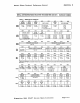
ACR - Auxiliary Control Register
ACR(7] - Baud Rate
Generator
Set
Select
-
This
bit
selects
one
of
two
sets
of
baud
rates to be generated by the BRG:
Set
1:
50,
110,
134.5,200,300,600,
1.0SK,
1.2K, 2.4K, 4.8K, 7.2K, 9.6K, and
38.4K baud
Set
2:
75,
110, 134.5,
150,300,600,
1.2K,
I.SK, 2.0K, 2.4K, 4.8K, 9.6K, and
19.2K baud.
The
selected
set
of
rates is available for·
use
by
the
channel
A and B receivers and
transmitters
as
described
in CSRA
and
CSAB. Baud rate
generator
characteristics
are given
If
table
3.
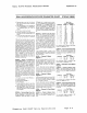
Table 3 BAUD RATE GENERATOR CHARACTERISTICS
CRYSTAL
OR
CLOCK = 3.6864MHz
I
NOMINAL
RATE(BAUD) ACTUAL 16X CLOCK (KHz) ERROA (PERCENT)
I
50
0.8 0
75
I 2 0
I
tl0
1.759
-0069
i
134.S
2.153 0.059
lSC
2.4 0
200
32
0
30e
48
0
600
9.6
0
1050
16756
-0.260
1200
19.2
0
1900
28.S
0
200·
32056
0.175
24:Je'
384
0
48,10
76.8
0
7200
115.2
0
9600 153.6
0
192K
3072
a
J8.4K
614.4
a
....
erE
0
....
''1
Cv"';18
.},
'tiX
:,OCIC''S,
50)0
!.
'~'.:I
Signe~ics
2681
DUART
Device
Speciiications
Page
H-ll