
Specifications


"ul~i
Slave
Product
Re£erence
Manual
Appendix
H
DUAL
ASYNCHRONOUS
RECEIVER/TRANSMITTER
(DUART)
SCN2681
SERIES
eRA
-
Chlnnll
A
Commlnd
Reglltlr
eRA
il
I
register
uled
to
lupply
com·
mands
to
channel
A.
Multiple
commands
can
be
lpecified
in
a
lingle
write
to
CRA
..
long
II
the
comm.nds
are
non·conflict·
lng,
e.g.,
the
'enable
transmitter'
and
'r.l.t
transmitter'
commands
cannot
be
lpeclfied
in
•
single
command
word.
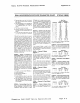
CRAIe:.)
-
Channll
A
Mllc.llanioul
CcNnrftIndl
- The
encoded
value
of
this
field
m.y
be
used
to
Ipecify
a
single
com·
mand
aa
follows:
CRA(t:4)
COMMAND
o 0 0
No
command.
o 0 1 Reset
MR
pointer.
Causes
the
channel
A MR
pointer
to
point
to
MR1.
o 1 0 Reset receiver. Resets
the
chan·
nel
A receiver
as
if
a
hardware
reset
had
been
applied. The
reo
ceiver
Is
disabled
and
the
FIFO
Is
flushod.
o 1 1 Reset
transmitter.
Resets
the
channel A
transmitter
as II a
hardware
reset had been ap·
plied.
1 0 0 Reset
error
status.
Clears
the
channel
A Received Break, Par·
Ity
Error,
Framing
Error,
and
Overrun Error
bits
in
the
status
register
{SRA(7:4)l. Used
in
char·
acter
mode
to
clear OE
status
(.Ithough
RB.
PE,
and FE
bits
will
also
be
cleared) and in
block
mode
to
clear
all error
status
after
a
block
of
data
has been
received.
1 0 1 Reset Channel A break
change
interrupt.
Causes
the
channel
A
broak
detect
change
bit
in
th€' in·
terrupt
status
register
(ISR(2J)
to
be cleared
te·
zero.
1 1
0 Start break
Forces
the
TXDA
output
low
(spacing).
If
ttl
0::
transmitter
is
empty
the
start
of
thl
br6ak
condition
will
be de·
layed
L;p
to
two
bit
times.
If
the
transmitter
Is
active
ttle
brea\<.
begins
when.transmission
of
thE:
character
is
completed.
If
a
cha',
acttr
is
in
the
THR,
the
start
of
the
break
will
be delayed
until
that
c~aracter,
or any
others
loaded
lubseQuently
are trans·
mitted.
The
transmitter
must
be
enabled
for
this
command
to
be
accepted.
1 1 1
Stop
S
rea
1<..
The TXDA line
wiil
go
high
(marking)
within
two
bit
times,
TXDA
will
remain high
for
one
bit
time
before
the
next
character,
if
any, is
transmitted.
CRAI3) -
Dllable
Channll
A
Tranlmltter
-
This
command
terminates
transmitter
operation
and
resets
the
TxRDY
and
TxEMT
stalus
bits.
However,
If
a
character
Is
being
transmitted
or
If
a character
is
in
the
THR when the
transmitter
is
disabled,
the
transmission
of
the
character(s)
is
completed
before
assuming
the
inactive
state.
CRA(2J
- Enable Channel A
Transmitter
- Enables
operation
of
Ihe
channel A
transmitter.
The TxRDY
status
bit
will
be
asserted.
CRA(1) -
Disable
Channel
A Receiver -
This
command
terminates
operation
of
the
receiver
immedialely
- a character
being
received
will
be
lost.
The
command
has
no
effect
on
the
receiver
status
bils
or
any
other
control
registers. II
the
special
multidrop
mode
is
programmed.
the
reo
ceiver operates even
if
it is disabled. See
Operation
section.
CRA[O)
- Enable Channel A
Rocoiv.r
-
Enables
operation
of
the
channel A &e.
ceiver. II
not
in the
special
wakeup mode.
thiS
also
forces the receiver
into
the
search
for
start·bit
state.
CRB
- Channel B Command
Register
CAB
IS
a
register
uSE;d
10 supply
com·
mands
to
ct,ar-ne
l
B.
Multiple
command~
can be speCified
in
a
single
write
to
CAB
as long as the
commands
are
non·conflict·
ing
e.g.. the 'enable
transmltler'
and
'reset
transmitter'
commands
cannol
be
specified
in a
single
command
\Nord.
The
bit
dcfiniti:)ns
fo~
th!s
reClsterart
identical
to
the
bit
definitions
fer eRA, ex·
ce;t
Ihal
a!1
control
actions
apI")'
to
the
channt'l B receiver and
transmitter
and
the
corresponding
ir,puls
and
outputs.
SRA
- Channal A Status
Register
SRA(7) - Channel A Received
Br.ak
-
ThiS
bil
indicates
that
an all zero character
of
the
programmed
length
has
beer,
re
. ceived Without a
stop
bit. Only a
single
FIFO pOSition is
occupied
when
is
break
IS
received
further
entries
10
the
FI
FO
are in·
hibited
until
the
RxDA line returns
to
the
marking
slate
for at least one·hall a
bit
time
(two
s;Jccessive edges
of
thc
inte'nal
or
extemal
h:
Clockl.
When
this
bit
IS
set,
the
channel
A
'change
in break'
bit
in
the
ISR (ISR[2)l
is
I8t.
ISR{2)
is
also
set
when
the
end
of
the
bruk
con·
dition,
as
defined
above,
is
detected.
The break
detect
circuitry
can
detect
breaks
that
originate
in
the
middle
of
a
received character. However,
If
• break
begins
in
the
middle
of
a cl'iilraCttr,
it
must
persist
until
at least
the
end
of
the
next
character
time
in
order
for
it
to
be
de·
tected.
SRA(6) - Channel A
Framing
Error
- ThiS
bit.
when set,
indicates
that
a
SlOP
bit
was
not
detected
when tt'le
correspondmg
data
character
an
the
FIFO was received. The
stop
bit
check
is made in
the
middle
ot
the
first
sto;>
bit
position
SRA[S) - Channel A
Parity
Error
- ThiS
bil
is set
when
the
'with
panty'
or
'force
parity'
mode
is
programmed
and
the
corre·
sponding
character
In
the
FIFO
was
reo
ceived
with
incorrect
parity.
In
lhe
special
multidrop
mode
the
parity
error
bit
stores
the
received AID
bit.
SRA(4) - Channel A Overrun Error -
This
bit,
when
set.
indicates
that
one
or
more
characters
in
the
received
data
stream
have been
lost.
It
is
set
upon
receipt
of
a
new
character
when
the
FIFO
is
full
and
a
character
is
already
In
the
receive
shift
register
waiting
for
an
empty
FIFO
posi.
tion.
When
this
occurs,
the
Character
in
the
receive
shift
register
(and
Its
break
detect,
..,arity error and
framing
error
status. if any) is
lost.
This
bit
IS
cleare~
b~'
a
'reset
error
statu!.'
command.
SRA[3} -
Channel
A
Transmitter
Empty
(TxEMTA) - TtliS
bit
Will be set
when
the
channei A
tranS"'ltler
underruns.
i.e.,
bott,
thE.'
transm:t
holdinG rewlster (THAI
and
the tranSrTtli shall
register
are
~mpty.
It
IS
se~
after
transmiSSion
of
tne
last
stop
bit
of
a
Characte~
II
no
character
IS
In
the
THR
awaiting
transmiSSion
It
IS reset
when
the
THA
is
loadec
b,
the CPU
or
wne!l
the
transmitter
is
disabled.
SRA(2)
-
Channel
A
Tranlmltter
R.ady
(TxRDYA) - ThiS bit. wher. sel,
indicates
that
the
THA
IS
empty
and
ready
to
be
loaded With a character. ThiS Olt
IS
cleared
wher. the THR is loaoed b)'
tfle
CPU
and
IS
set when
thE;
character
IS
tra"lslerred
to
the
transmit
Shift register. TxRDV
is
rese:
when
the
transmitter
IS
disabled
and
is
set
when the tranS'TIltter
IS
first
enabled.
VIZ.,
characters
loaded
Into
the
THA
while
the
transmll1e~
IS
d'Si'blej
wli. nI)l be
tra~s·
mltte"
Sign.tics
2681
DUART
Device
5peci£ications
Page
H-10