
Specifications


Multi
Slave
Product
Re£erence
Hanual
Appendix
H
DUAL
ASYNCHRONOUS
RECEIVER/TRANSMITTER
(DUART)
SCN2681
SERIES
3.
Received data
IS
not sent
to
the
local
CPU, dnd the error
status
conditions
are Ir.actlve.
4.
The received parity is
not
checked and
is
not
reg'3nerated
for
transmission,
i.e.,
transmitted
parity
Cit
IS
as
reo
cel"ed,
5.
Ttie receiver
must
be enabled.
6.
Charac~er
framing is not checked, and
tne
stop
bits
are
retransmitted
as
reo
Cel\leCl.
7.
A recel·,ed break
IS
echoed as
r~cel·,ed
untli
tne next valid :itart
bit
is
detected.
The
user
must
exercise care
.....
r.en
switch·
ing
Into
and out
of
the ·Yarious modes The
seiected
mcde
woll
be activated immel.ll·
ately u;>on mode selection, even
if
this
oc·
curs
,n
t~e
m.dd!e
of
a received or trans-
mitted
character. LikeWise, If a
mcde
is de-
selected,
tne
device will 3Wltch
out
of
the
mode
immediately
An e)(ceotion
to
this
IS
switching
out
of
autoechO
or
remote
loop-
back
modes:
if
the de-selection
occurs
just
after
the receiver has sampled the
stop
bit
(indicated
In
autoecho
by asser-
tion
ofAxADY),
and the
transmitter
is
enabled, the
transmitter
Will remain in
autoecho
mode
until
the
entire
stop
bit
has ceen
retransmitted.
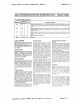
MR2A(S) - Channel A
Transmitter
Re-
que.t·to-Send
Control
- This
bit
controls
the
deactivation
01
the ATSAN
output
(OPO)
by
the
transmitter.
This
output
is
normaily
asserted by
setting
OPA[O)
and
negated by
resetting
OPA[O).
MA2A(5):: 1
caLlses
OPR[O)
to be reset
,mtomat:call,
one
bit
time
after
the characters in the
channel
A.
:ransmlt
s~dt
register
and In
the
THA, " an'(, are
completely
transmit-
ted,
,ncludlng
tne ;:lrogrJmmed
nllmber
of
stop
bits,
If
the
transmitter
IS
not enabled.
This feature .:an be used
to
al.tomati~al!y
terminate
the transmiSSion
of
a
message
as
follows:
1.
Program a.Jto·reset mode: MR2A.(51=
1.
2,
Enable
transmitter.
3.
Assert
RTSAN:
OPA[O)
=
1.
4.
Send message.
5.
Disable
transmitter
after
the last char-
acter
is
loaded
Into
the channel A THR.
6.
The last character will be
transmitted
anCl
OPR[O)
will be reset one
bit
time
after
the last
stop
bit,
causing
RTSAN
to
be negated.
MR2A(4) -
Chann.1 A Clear·to,Send Con-
trol
-
If
this
bit
IS
0,
CTSAN
ras
no
elfect
on
the
transmitter.
If
this
bit
IS
a 1
•.
the
transmitter
Checks
the
state
of
CTSAN
(I
PO)
each
time
it
is ready
to
send a charac-
ter.
If
IPO
is asserted (low), the
character
is
transmitted.
If
it
is negated (high), the
TxDA
output
remains in the marking
state
and the
transmission
is delayed
until
CTSAN goes low. Changes ,n CTSAN
""hile
a character is being
transmitted
do
not
allect
the
transmission
of
that charac-
ter.
MR2A(3:0) -
Channel A
Stop
Bit
Length
Select - This field
programs
the
length
of
Ihe
stop
bit
appended
to
the
transmitted
character. Stop
bit
lengths
at
9/16 to 1 and
1·9"6
to
2 bits.
111
Increments
of
1/16 oit,
can be programmed for character
lengths
016,
7.
and 8 bits. For a character
length
of
5
tJltS,
1·1/16
to
2
stop
bits
can be pro-
grammed In
increments
of
.1i1S
bit. The
re-
ceiver
o~ly
checks
for
a 'marl('
condition
at the
center
of
the first
stop
bit
pOSition
(ere
bit
time
after
the last
data
bit,
or
after
tt'e parity
bit
if
parity
is
enabled) in all
cases.
I f
an
external 1 X
clock
is used
for
the
transmitter,
MA2A(3) = a
selects
one
stop
bit
and MA2A(3) = 1
selects
two
stop
bits
to be transmitted.
MR1 B -
Channel
B
Mode
Register
1
MA 1 B
IS
accessed when tne channel B
MR
pOI"ter
POints to MA1. The pOinter
IS
set
to
MR1
by
RESET or by a
'set
pOln:er' com-
mand
applied
via CRB.
After
reading
or
wYfltlr.g
MR
1
B,
the
pointer
will
point
to
MR2B
The
bit
·jefinltlons
lor
this
register are
,dentlcal
to
the bit
definitions
lor
MR1A,
~x.~~pt
that all
,~ontrol
act,ons
apply
to
the
ch:lnnel B receiver and
t~ansmltter
and the
.:;.:;rrespo~dlng
inputs
and
outputs.
M R2B -
Channel
B
Mode
Register
2
'.1R2B is accessed when the channel B MA
pOinter pOints to MR2,
which
occurs
after
any ,lccess
to
MR 1
B.
Accesses to
MA2B
,jo
not change the pointer.
The
Olt
deflrltlons
for thiS register
::Ire
identical
to
the bit
definitions
for MR2A,
except that
all
control
actions
apply to the
channel B receiver and
transmitter
and the
corresponding
inputs
arij
outputs.
CSRA
-
Channel
A
Clock
Select
Register
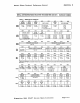
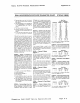
CSRA(7:4! - Channel A
Recel".r
Clock
Select - This field
selects
the baud rate
clock
for
the channel A receiver as
101-
lows:
Signetics
2681
DUART
Device
Spec1i~cationa
Baud Rate
CLOCK = 3.6864MHz
CSRA(7:4)
ACR[71
=0
ACR[71.1
0
a a
0 50
75
a
()
a
1
110
110
a
a
1
a
134.5
1345
0
a 1 1 200
150
a
a
a
300 300
a
a 1 000 600
a a
1,200 1,200
0
1
1 1
1,050
2.000
a a a
2,400 2.400
0 0
1 J 800
4800
a a
7,200
1,800
a
1
1
9,600 9,600
11
a
38.4K 19.2K
a 1
Timer
Timer
a
IP4-16X
IP4-16X
IP4-1X
IP4-1X
The receiver
clock
is always a 16X
clock
ex.cept for CSRA[7:4) = 1111.
CSRA(3:0) - Channel A
Transmitter
Clock
Select - This field
selects
the
baud rate
Clock
lor
the channel A
transmitter.
The
field
definition
is as per CSRA(7:4)
except
as
follows:
CSRA(3:0)
1 1 a
1 1 1 1
Baud Rate
ACR[7) = 0
ACR[71
= 1
IP3-16X
IP3-1X
IP3-10X
IP3-1X
The
transmitter
clock
is always a 16X
clock
except
lor
CSRA[3:0] = 1111.
CSRB
-
Channel
B
Clock
Select
Register
CSRB[7:4) - Channel B Receiver
Clock
Select
- This field selects
the
baud rate
clock
for the channel B receiver. The
field
delinltlon
15
as per CSRA[7:4)
except
as
fellOWS·
CSRB(7:4)
, 1 I a
1 1 1 1
Baud Rate
ACR(7) = 0
ACR[71
= 1
IPS-lOX
IP6-IX
IP6-16X
IP6-1X
T~e
r~celver
clock
IS
always a
16X
clock
except
for CSRB[7.4) = 1 I 1
1.
CSRB(3:0)-
Channel B
TransmItter
Clock
Select
- This field selects the baud rate
clcck
for
Ihe
channel B
transmitter.
The
lield
rjeflnitlon
is
as
per CSAA(7·4]
except
as follows:
CSRB[J:O)
1 1 a
1 1 , 1
Baud Rate
ACR(7) = 0
ACR[71
= 1
IP5-16X
IP5-1X
IP5-16X
IP5-1X
The
transmitter
c:ock
19
always a
l6X
clocK except for CSRB[3:01 = 1111.
Page
H-9